
Robust communications antenna

a communications antenna and antenna technology, applied in the direction of antennas, elongated active elements, electrical devices, etc., can solve the problems of inability to mount a right angle antenna on a metallic surface, antennas are continuously challenged, and antennas are prone to damage, etc., to achieve good electromagnetic performance and resistance

Inactive Publication Date: 2009-03-19
QUIST GREGORY M +1
View PDF1 Cites 1 Cited by
  • Summary
  • Abstract
  • Description
  • Claims
  • Application Information

AI Technical Summary

Benefits of technology

[0007]The present subject matter addresses the above concerns by disclosing an antenna design that incorporates both good electromagnetic performance and resistance to damage. Such an antenna can be installed on metallic or non-metallic enclosures, utility vault covers, manhole covers, equipment cases, walls, roofs, flagpoles, light poles, electrical and other utility poles, doors, window

Problems solved by technology

Antennae are used for a wide range of radio communications applications and are often deployed in places where they can be damaged.
Such antennae are successful, but are prone to damage by vandals and common usage.
In some cases it is not possible to mount a right angle antenna on a metallic surface.
Such an antenna is continuously challenged by traffic impacts.
This provides superior defense against damage, but often compromises its electromagnetic performance.

Method used


Image

  • Robust communications antenna
  • Robust communications antenna
  • Robust communications antenna

Examples


Embodiment Construction

[0014]In the following detailed description, reference is made to the accompanying drawings, which form a part hereof, and in which are shown by way of illustration specific embodiments in which the subject matter may be practiced. In this regard, terminology such as “first,”“then,”“afterwards,”“before,”“next,”“finally,”“above,”“below,”“top,”“bottom,”“front,”“back,”“leading,”“trailing,” etc., is used with reference to the drawing being described. Because the processes and methods of the present subject matter can be performed in a number of different orders, and because the individual elements of the apparatus and systems of the present subject matter may be configured in a number of different orders, the above terminology is used for purposes of illustration and is in no way limiting. It is to be understood that other embodiments may be utilized and logical changes may be made without departing from the scope of the present subject matter. The following detailed description, theref...


PUM

PropertyMeasurementUnit
Angleaaaaaaaaaa
Lengthaaaaaaaaaa
Dielectric polarization enthalpyaaaaaaaaaa

Abstract

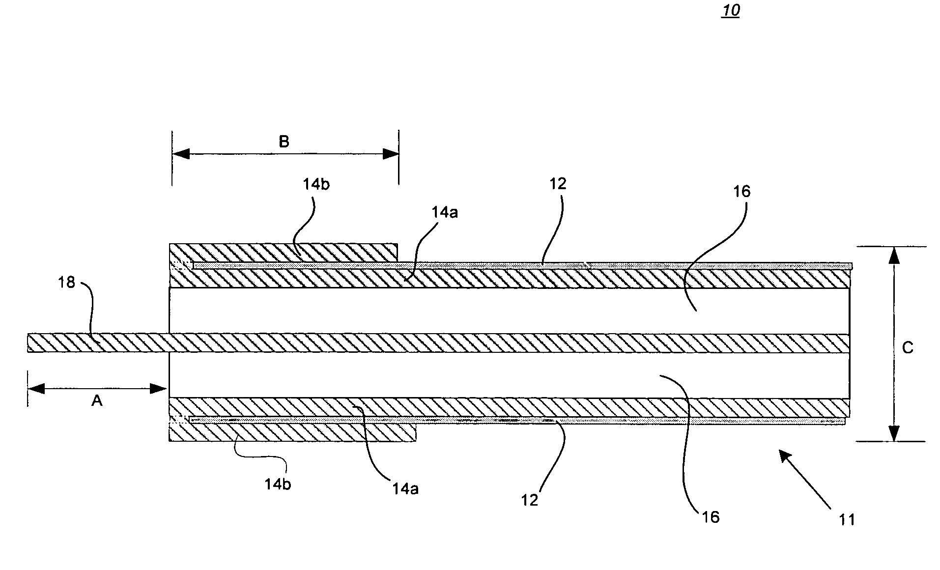
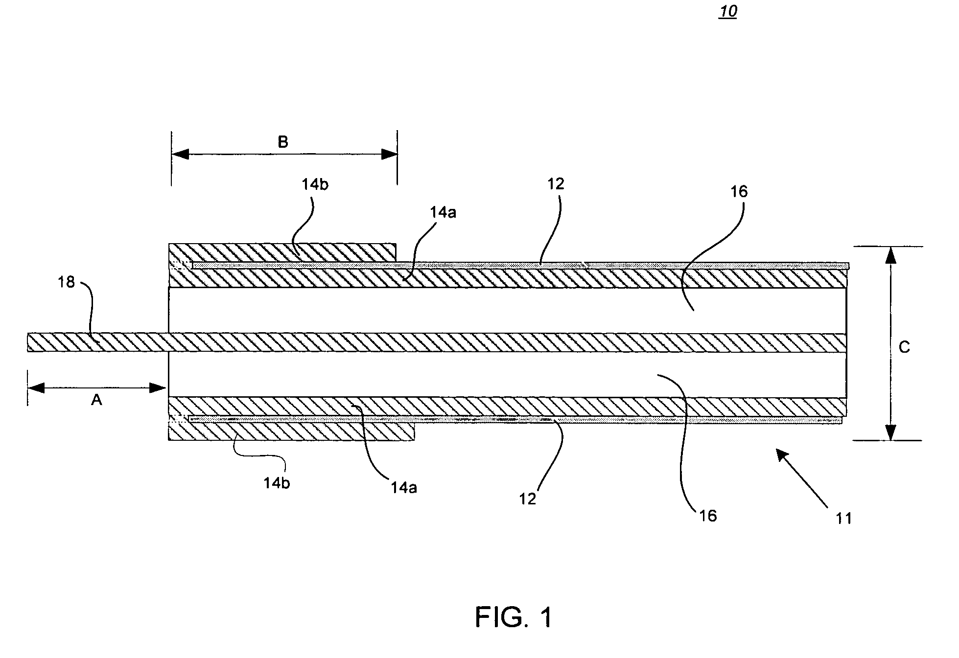
A robust low profile antenna well suited for deployment on the lids of cavities, such as manholes is described. The antenna is constructed from a coaxial cable for use proximate to a structural surface. The antenna is formed by folding back an outer metallic braid of an end of the coaxial cable to a length that approximately matches ¼ of a wavelength of a desired operating frequency times a velocity factor of the coaxial cable. Next, the radiative element is formed by exposing the center conductor from the end of the coaxial cable to a length that approximately matches ¼ of the wavelength of the operating frequency multiplied by the composite velocity factor being based on a dielectric encasing of the coaxial cable and the distance of the antenna from the structural surface. The antenna is oriented substantially parallel to the structural surface. The resulting antenna is of a comparable size to the coaxial cable.

Description

CROSS-REFERENCE TO RELATED APPLICATIONS[0001]This application claims the benefit of U.S. Provisional Patent Application No. 60 / 963,740, filed Aug. 7, 2007, the contents of which are hereby incorporated by reference in its entirety.BACKGROUND OF THE INVENTION[0002]1. Field of the Invention[0003]The present application relates to methods and apparatuses for communications, and, in particular, to methods and apparatuses for a robust antenna system / design capable of operating in environmentally hostile conditions.[0004]2. Related Art[0005]Antennae are used for a wide range of radio communications applications and are often deployed in places where they can be damaged. In many antenna applications the radiative element of the antenna is placed at right angles, often vertical, to a structural surface. The intent is to create a dipole radiator by the reflection of a driven element from a conductive metallic surface. This is commonly seen in roof top mounting of radio antennae on vehicles. ...

Claims


Application Information

Patent Timeline
IPC IPC(8): H01Q9/04H01P11/00
CPCY10T29/49016H01Q9/30
Inventor QUIST, GREGORY M.DRAKE, DAVID A.
Owner QUIST GREGORY M
Learn More