Metal nano-particles coated with silicon oxide and manufacturing method thereof

Inactive Publication Date: 2006-09-14
MIJINANOTECH
View PDF2 Cites 18 Cited by
  • Summary
  • Abstract
  • Description
  • Claims
  • Application Information

AI Technical Summary

Benefits of technology

[0011] Therefore, the present invention has been made in view of the above problems, and it is an object of the present invention to provide a surface-stabilized metal nanoparticle comprising a nanosized metal and a silicon oxide surrounding the nanosized metal wherein the

Problems solved by technology

The gas phase method involves considerable manufacturing costs and is disadvantageous in terms of poor productivity and workability.
However, these metal nanoparticles are unstable and agglomerate with the passage of time, eventually losing their nanoparticle characteristics.
In the case of metal nanoparticles synthesized by introducing the linear organic molecular compound into the surface of the metal, the metal nanoparticles can react

Method used


Image

  • Metal nano-particles coated with silicon oxide and manufacturing method thereof
  • Metal nano-particles coated with silicon oxide and manufacturing method thereof
  • Metal nano-particles coated with silicon oxide and manufacturing method thereof

Examples


example 1

[0045]

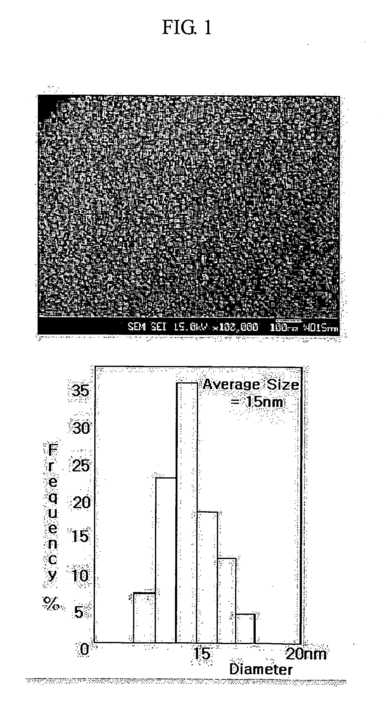
[0046] Referring to the reaction scheme above, 100 ml (0.1 moles) of 1 M Ag solution, 100 ml of distilled water and 20 g (1.22 moles) of β-alanine were mixed and dissolved. To the solution were added 400 ml of methanol, 200 ml of ethoxyethanol and 200 ml of diethylene glycol. After the resulting mixture was stirred until it was completely clear, a silicon compound or a derivative thereof was added to the solution and stirred to obtain a clear solution. After completion of the hydrolysis of the silicon compound or a derivative thereof, 10 g of triethanolamine and 100 g of ammonia water were sequentially added to form a complex compound. To the solution was added 100 ml (2.0 moles) of hydrazine monohydrate (H2NNH2.H2O) to reduce the Ag particles.

[0047] The reduced Ag particles were filtered, and washed with 300 ml of distilled water six times, 300 ml of a solution of ethanol and distilled water (1:1 (v / v)) three times and 300 ml of ethanol to completely remove impurities presen...

example 2

[0048]

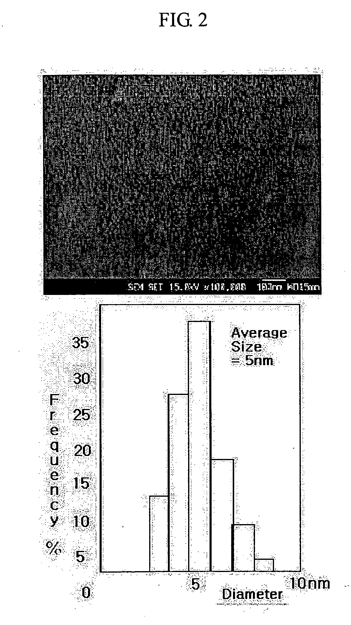
[0049] Referring to the reaction scheme above, 100 ml (0.1 moles) of 1 M Au solution, 100 ml of distilled water and 20 g (1.22 moles) of β-alanine were mixed and dissolved. To the solution were added 400 ml of methanol, 200 ml of ethoxyethanol and 200 ml of diethylene glycol. After the resulting mixture was stirred until it was completely clear, a silicon compound or a derivative thereof was added to the solution and stirred to obtain a clear solution. After completion of the hydrolysis of the silicon compound or a derivative thereof, 10 g of triethanolamine and 100 of ammonia water were sequentially added to form a complex compound. To the solution was added 100 (2.0 moles) of hydrazine monohydrate (H2NNH2.H2O) to reduce the Au particles.

[0050] The reduced Au particles were filtered, and washed with 300 ml of distilled water six times, 300 ml of a solution of ethanol and distilled water (1:1 (v / v)) three times and 300 ml of ethanol to completely remove impurities present in ...


PUM

PropertyMeasurementUnit
Temperatureaaaaaaaaaa

Abstract

Disclosed herein is a metal nanoparticle whose surface is coated with a silicon oxide. The silicon oxide is obtained from a silicon compound or a derivative thereof as a precursor and has a particle diameter of a few angstroms (A). Further disclosed is a method for manufacturing metal nanoparticles. The method comprises the steps of a) mixing metal ions, a solvent and an additive required for forming metal complex ions, b) adding a silicon compound or a derivative thereof as a precursor for forming silicon oxides, to the mixture of step a) to coat the surface of the metal ions, and c) adding a reducing agent to the mixture of step b) to reduce the metal ions. If necessary, the method further comprises the step of d) lyophilizing the resulting product of step c), i.e. metal nanoparticles. Since the surface of the metal nanoparticle of the present invention is coated with a silicon oxide, the metal nanoparticle is stabilized. In addition, the metal nanoparticle retains electromagnetic properties inherent to the metal and can be easily manufactured in an economical manner.

Description

TECHNICAL FIELD [0001] The present invention relates to a metal nanoparticle whose surface is coated with a silicon oxide, and a method for manufacturing the metal nanoparticle. More particularly, the present invention relates to a stabilized metal nanoparticle comprising a nanosized metal and a silicon oxide surrounding the nanosized metal wherein the silicon oxide is obtained from a silicon compound or a derivative thereof as a precursor and has a particle diameter of a few angstroms (Å), and a method for manufacturing the metal nanoparticle. BACKGROUND ART [0002] Nanoparticles refer to particles having a diameter on the order of nanometer scale (1˜100 nm). Materials within this diameter range are in intermediate states between bulky metals and molecular metals. Despite the same chemical composition, these materials exhibit optical and electromagnetic properties different from bulky states due to their drastically increased specific surface area and quantum effects. [0003] In this...

Claims


Application Information

Patent Timeline
IPC IPC(8): B05D7/00B32B5/16B82B3/00B22F1/054B22F1/16B22F9/24C09C1/62C09C3/06C09C3/12
CPCB22F1/0018B22F1/02B22F9/24B82Y30/00Y10T428/294C09C1/62C09C3/063C09C3/12Y10T428/2993C01P2004/64B22F1/054B22F1/16B82B3/00B82Y40/00C09C3/06
Inventor KANG, DAE SAM
Owner MIJINANOTECH
Why Eureka
Try Eureka