Precisively butting apparatus for photoelectric device package

A technology for optoelectronic devices and docking devices, which can be used in piezoelectric/electrostrictive/magnetostrictive devices, electrical components, microstructure devices, etc.

Inactive Publication Date: 2005-05-11
UNIV OF ELECTRONICS SCI & TECH OF CHINA
View PDF0 Cites 9 Cited by
  • Summary
  • Abstract
  • Description
  • Claims
  • Application Information

AI Technical Summary

Problems solved by technology

At present, there are not many literature reports on the automatic packaging of optoelectronic devices. As far as the inventor knows, there are almost no patent documents on the precision docking device for optoelectronic device packaging.

Method used


Image

  • Precisively butting apparatus for photoelectric device package
  • Precisively butting apparatus for photoelectric device package
  • Precisively butting apparatus for photoelectric device package

Examples


Embodiment 1

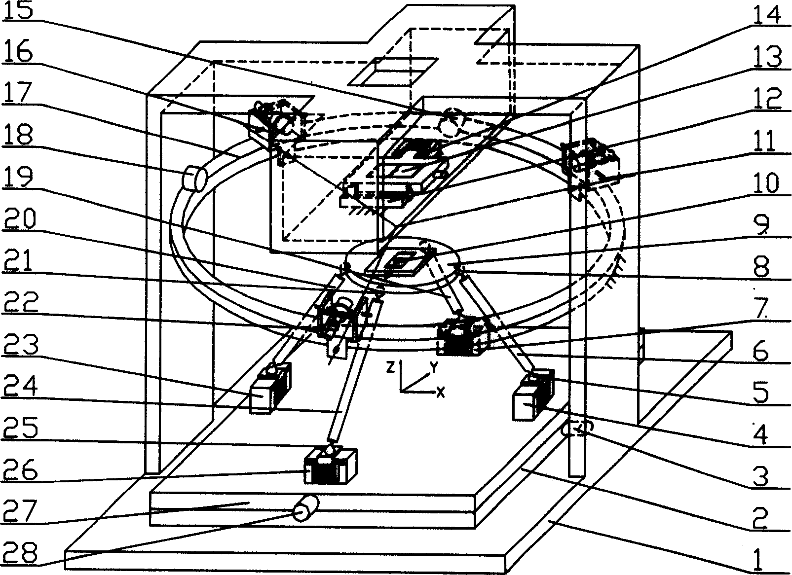
[0028] attached figure 1 is an embodiment of the present invention. This precision docking device for optoelectronic device packaging consists of a base (1), a moving platform (9), fixed length rods (6, 19, 20, 24), positioning seats (4, 7, 23, 26), micro It is composed of a displacement driver, a two-way translation platform (2, 27), an optical fiber clamp (10, 13) and the like. The base 1 and the moving platform 9 are connected by 4 fixed-length rods, one end of the two fixed-length rods (6, 20) is connected with the parallel plate moving pair on the positioning seat (4, 23) through the rotating pair, The other end is connected with the moving platform (9) through a ball joint, and one end of the other two fixed-length rods (19, 24) is connected with the parallel plate moving pair on the positioning seat (7, 26) through a Hooke joint or a ball joint. The other end is connected with the moving platform (9) through a ball joint, thereby forming a spatial parallel mechanism. ...

Embodiment 2

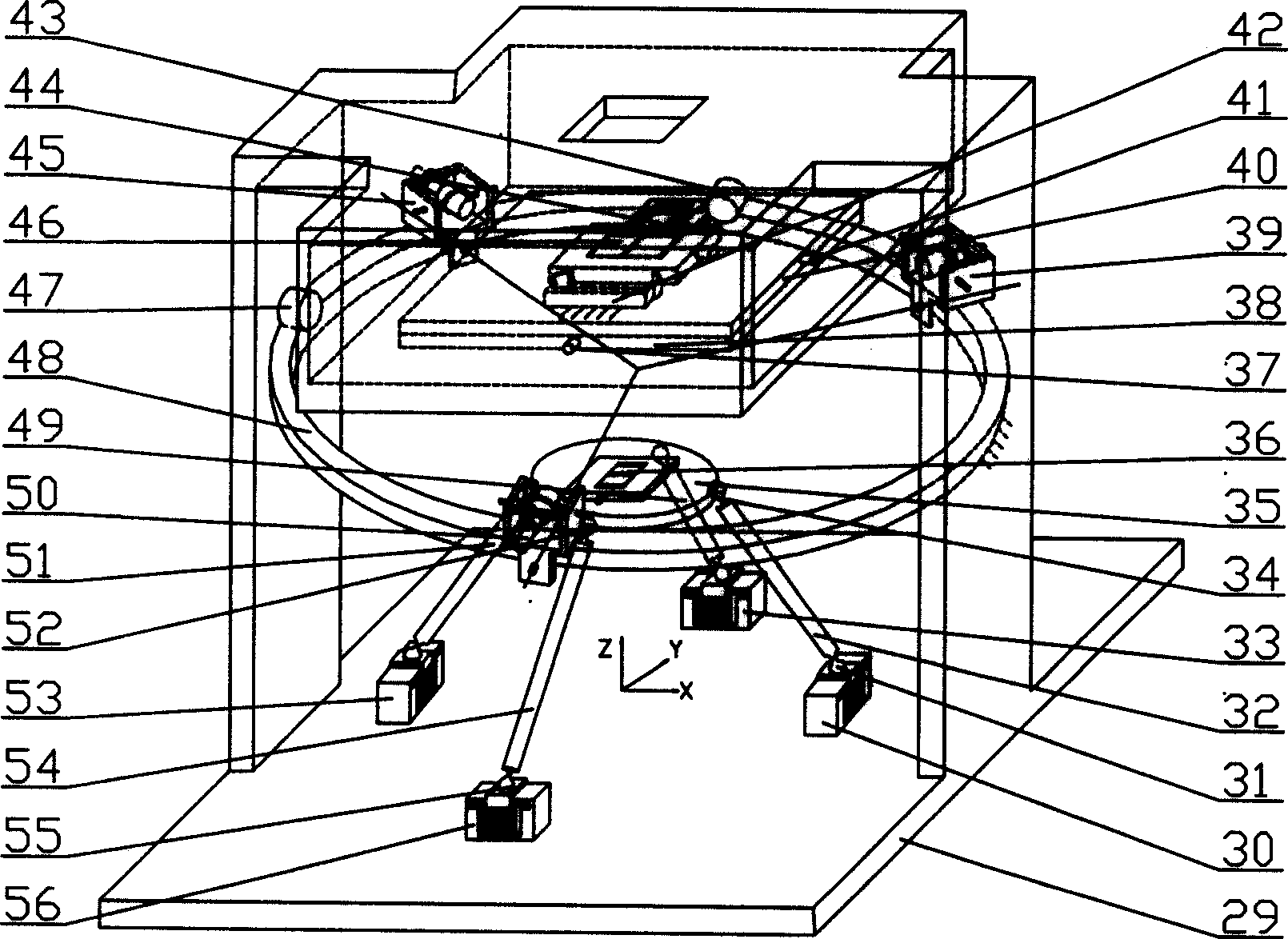
[0030] attached figure 2is another embodiment of the present invention. It consists of a base (29), a moving platform (35), a fixed length rod (32, 49, 51, 54), a positioning seat (30, 33, 53, 56), a micro-displacement driver, and a two-way translation platform (38, 40 ) and optical fiber clamps (36, 46) and other components. The base 29 and the moving platform 35 are connected by four fixed-length rods, one end of the two fixed-length rods (32, 51) is connected with the parallel plate moving pair on the positioning seat through a rotating pair, and the other end is connected through a ball joint. Linked with the moving platform (35), one end of the other two fixed length rods (49, 54) is connected with the parallel plate moving pair on the positioning seat through a Hooke hinge or a spherical hinge, and the other end is connected with the moving platform (35) through a spherical hinge. ) to form a spatial parallel mechanism. The positioning seat is provided with a micro-d...


PUM


Abstract

The invention consists of a base, a two-way translational platform, four locating beds, an actuated platform, a length control bar, a top optical fiber champing device and a bottom optical fiber champing device. The one end of length control bar is connected with the actuated platform through ball pivot and the other end of length control bar is connected with two locating beds through revolving joint. The length control bar is connected with another two locating beds through hooke articulation or ball pivot to form parallel space closed chain device.

Description

Technical field [0001] The invention belongs to the technical field of optical-mechanical-electrical integration, and in particular relates to the precise packaging technology of optoelectronic devices. Background technique [0002] Packaging has a great relationship with the reliability of optoelectronic devices, and the packaging cost of optoelectronic integrated devices accounts for about 70-90% of the total cost. Automatic docking device and technology is the key technology of optoelectronic device packaging, which can reduce production cost, improve production efficiency and ensure device quality. In the research of precision micro-motion docking mechanism, the parallel mechanism has attracted people's attention, mainly because the parallel mechanism has the following advantages: (1) compact structure (2) simple design and processing, and low sensitivity to temperature (3) drive It can be placed on the pedestal (4) The error accumulation and amplification are small (5)...

Claims


Application Information

Patent Timeline
Patent Type & Authority Applications(China)
IPC IPC(8): B81C99/00H01L21/50H01L21/56
Inventor 范守文李辉吴献钢陈畅袁太文洪涛
Owner UNIV OF ELECTRONICS SCI & TECH OF CHINA
Why Eureka
Try Eureka