Supercharge Your Innovation With Domain-Expert AI Agents!

Loading device to transfer items from a movable platform

A technology of loading equipment and mobile equipment, applied in the direction of conveyor objects, transportation and packaging, conveyor control devices, etc., which can solve the problems of manual labor of employees

Inactive Publication Date: 2005-07-27
RESTAURANT TECH
View PDF1 Cites 2 Cited by
  • Summary
  • Abstract
  • Description
  • Claims
  • Application Information

AI Technical Summary

Problems solved by technology

The disadvantage of manually transferring food from the freezing member to the cooking member is the manual labor required by the employee

Method used


Image

  • Loading device to transfer items from a movable platform
  • Loading device to transfer items from a movable platform
  • Loading device to transfer items from a movable platform

Examples


Embodiment Construction

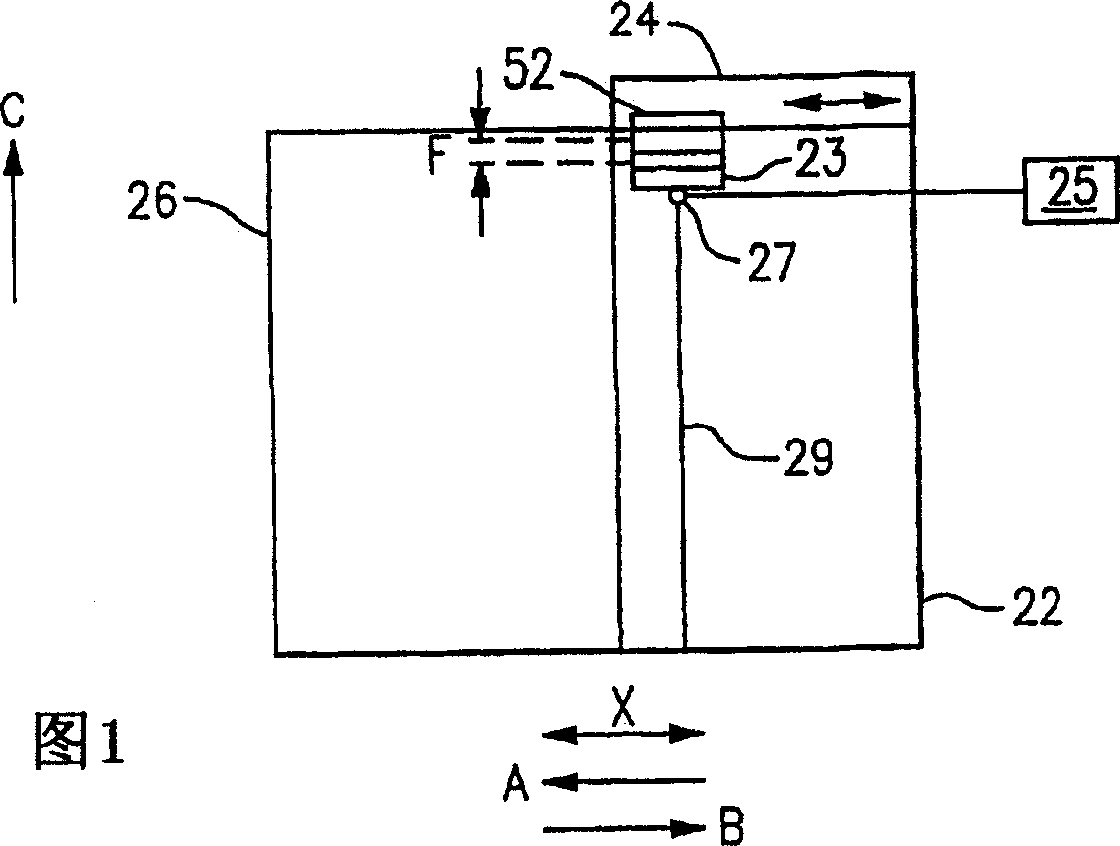
[0015] As shown in FIG. 1 , the loading device 24 is used to transfer items 52 from the first member 22 to the second member 26 according to the demand for the items 52 . In one embodiment, the first member 22 is a freezing member and the second member 26 is a cooking member, and the loading device 24 is used to transfer items 52, such as food.

[0016] Figures 2 to 4 An embodiment of a loading device 24 is schematically shown in . The illustrated loading device 24 includes a motor 70 that can move in the X direction (i.e. Figures 2 to 4 The feeder 66 that moves in the left and right direction). The feeder 66 includes a cutout 68 extending partially across the height h of the feeder 66 . Cutout 68 is preferably the same shape as article 52 . A sensor 72 is located on an upper surface 74 of the cutout 68 .

[0017] image 3 The feeder 66 is shown in the loading position. When the article 52 moves into the cutout 68 and the sensor 72 detects that the article 52 is locat...


PUM


Abstract

A loading device (24) includes a feeder (66) having a cutout (68) and a sensor (72). When a sensor detects that an item (52) is positioned in the cutout, a motor (70) slides the feeder out of a first component (22) to remove the item from the first component for delivery to a second component (26). Alternatively, the loading device is a pivotal arm (226) which pivots to slide the item out of the first component.

Description

technical field [0001] The present invention broadly relates to a loading apparatus for transferring items, such as frozen food, from a movable platform of a first member to a second member on demand for the items. Background technique [0002] When preparing food for hospitality, it is common to manually move the food from the freezing unit to the preparation area. For example, when preparing frozen food for hospitality, such as hamburger patties, it is common for food preparers to manually transfer the food from the freezing member to the cooking member. A disadvantage of manually transferring food from the freezing member to the cooking member is that it requires manual labor by employees. The user must remove the frozen food and transfer the food to the cooking member for cooking. [0003] There is therefore a need for a loading device that automatically transfers food from a freezing member to a cooking member upon a signal that food is required. Contents of the inv...

Claims


Application Information

Patent Timeline
Patent Type & Authority Applications(China)
IPC IPC(8): B65G47/08B65G43/08B65G47/82G07F9/10
CPCB65G47/82B65G2203/042B65G43/08G07F9/10
Inventor 杰弗里·L·桑兹杰克·佩利卡纳詹姆斯·D·康林托马斯·J·弗兰肯安德鲁·保罗·富兰克林兰迪·L·金纳罗纳德·J·格拉万斯科特·A·格拉韦戴维·A·希尔迈克尔·J·纽伯里曼纽尔·卡尔扎达亨利·托马斯·艾瓦尔德
Owner RESTAURANT TECH
Features
  • R&D
  • Intellectual Property
  • Life Sciences
  • Materials
  • Tech Scout
  • Unparalleled Data Quality
  • Higher Quality Content
  • 60% Fewer Hallucinations
Learn More