
Backlight module structure

A backlight module and support structure technology, applied in optics, nonlinear optics, identification devices, etc., can solve the problem that the backlight module cannot use flat display devices, etc.

Inactive Publication Date: 2005-09-07
AU OPTRONICS CORP
View PDF0 Cites 1 Cited by
  • Summary
  • Abstract
  • Description
  • Claims
  • Application Information

AI Technical Summary

Problems solved by technology

Such a backlight module with uneven backlight cannot be applied to a flat panel display device

Method used


Image

  • Backlight module structure
  • Backlight module structure
  • Backlight module structure

Examples


Embodiment Construction

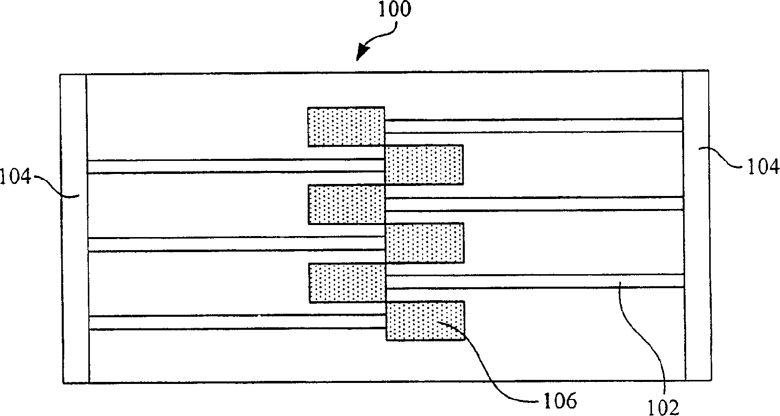
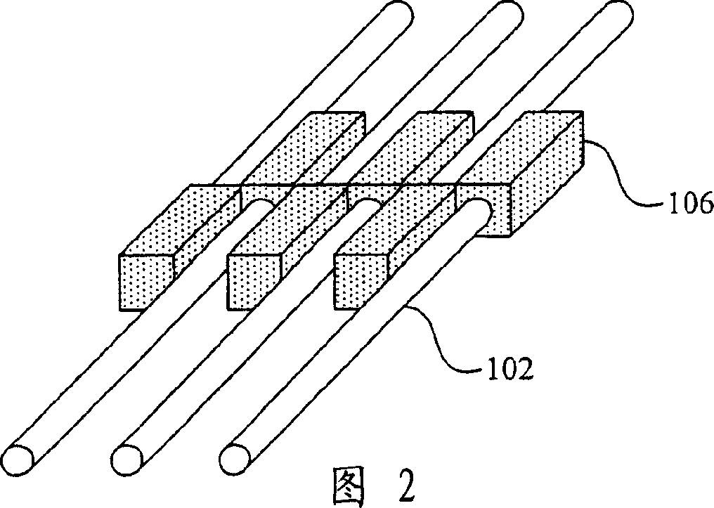
[0029] In order to make the structure of the backlight module provided by the present invention more clear, in several embodiments of the present invention, different supporting structures are taken as examples to describe in detail how to implement the present invention. Of course, the present invention is not limited to the disclosed embodiments. Any supporting structure that can make incident light in a single direction generate reflected light in different directions, and can make the reflected light uniform as disclosed in the embodiments of the present invention should fall within the scope of the present invention. In the above implementation manner, only a partial perspective view of the staggered arrangement of lamp tubes of the backlight module is taken as an example for illustration.

[0030] Please refer to Figure 4 to Figure 6 , which are partial perspective views of the staggered lamp tube arrangement of the backlight module according to a preferred embodiment o...


PUM


Abstract

The invention discloses an apheliotropic module framework adapted for plan display device, which at least comprises a deflector plate; two support boards, a plurality of supporting structures and light sources. The support boards are separately located in the relative sides of deflector plate. Several support structures in the form of two rows in parallel and stagger arrangement are set in midcourse of deflector plate and parallel to the said support boards. Each sight source is set in each one of support boards and support structures. The said support structures can make unidirectional incoming rays arise reflected rays in diversity directions to uniform the reflected rays.

Description

technical field [0001] The invention relates to a backlight module structure, in particular to a backlight module structure suitable for flat display devices. Background technique [0002] The backlight module is one of the basic components of a liquid crystal display (Liquid Crystal Display; LCD). Since the liquid crystal itself does not emit light, a backlight must be added behind the LCD panel (Panel). Most of the backlight is cold cathode fluorescent lamp (Cold Cathode Fluorescent Lamp, CCFL). The light emitted by the backlight passes through the LCD panel (Panel) and enters the human eyes to form an image. Liquid crystal, color filter (ColorFilter), polarizer (Polarizer) and other related parts. That is to say, the liquid crystal display must use the backlight to emit light. The light first passes through the first polarizer and then passes through the liquid crystal. The change of the voltage is used to change the arrangement of the liquid crystal molecules, and then...

Claims


Application Information

Patent Timeline
IPC IPC(8): G02F1/13357G09F9/35
Inventor 许时嘉林怡君
Owner AU OPTRONICS CORP
Learn More