Split display image edge blending method for large screen

A splicing display and image edge technology, which is applied in the direction of image communication, color TV parts, TV system parts, etc., can solve the problem of destroying the overall effect of the image, and achieve high resolution, excellent brightness modulation method, and soft brightness The effect of the transition effect

Inactive Publication Date: 2005-10-26
GUANGDONG VTRON TECH CO LTD
View PDF0 Cites 58 Cited by
  • Summary
  • Abstract
  • Description
  • Claims
  • Application Information

AI Technical Summary

Benefits of technology

This patented technology allows for smoother displays that are brighter than previous methods while also maintaining good resolution. It achieves this by create an evenly shaded surface on top of another smooth layer called prismatic layers. By doing it at certain angles, these surfaces will have different colors depending upon how much light they hit them during reflection from their original position. Overall, this new design improves overall performance and quality of displayed images.

Problems solved by technology

In existing technology, these techniques have limitations such as requiring longer exposure times during imagery projection, which causes breakage issues if adjacent screens get too much illumination compared to their central portion. Additionally, current methods require expensive equipment like cameras and mirror systems, making them costly.

Method used


Image

  • Split display image edge blending method for large screen
  • Split display image edge blending method for large screen
  • Split display image edge blending method for large screen

Examples


Embodiment Construction

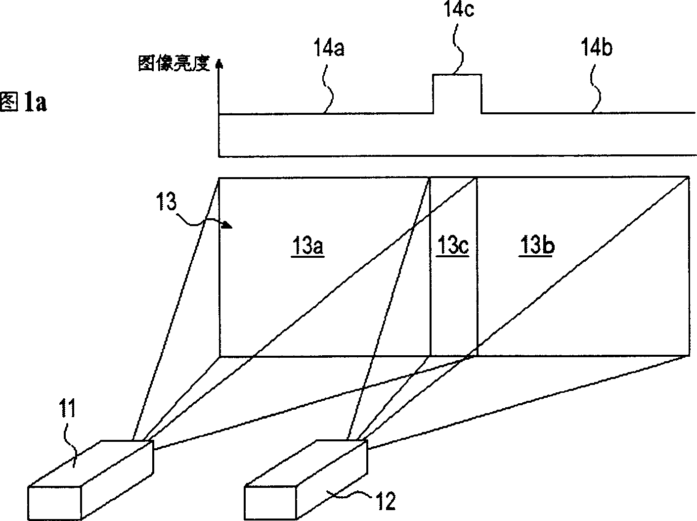
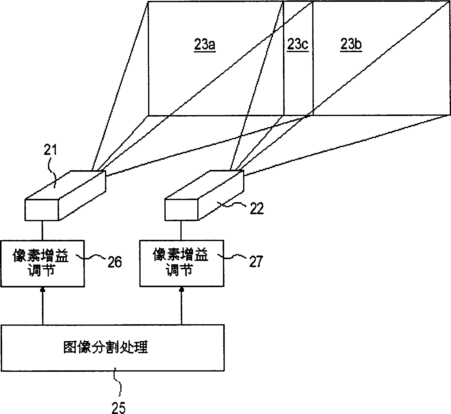
[0030] figure 1 It shows the situation that two projectors 11, 12 are used to stitch images on a large screen. Different from the prior art, the images projected by the two projectors have overlapping parts. Utilize a processor with a plurality of graphic display output channels to divide the picture to be displayed into two left and right sub-images 13a and 13b, and the two sub-images have an overlapping area 13c at the adjacent joint, as shown in the left image 13a in the figure There will be an area 13c displaying the same content as the left edge of the right image in the edge portion connected to the right image 13b. Both the left image 13a and the right image 13b contain content 13c. When the two projectors are combined to project the picture, there is an overlapping area in the projecting range of the boundary that connects with each other, so as to ensure that the adjacent image repeating display parts 13c can overlap each other accurately.

[0031] The image in the ...


PUM


Abstract

This invention discloses a stitching displayed image edge interfusion method on a large screen, which applies multiple projecting machines to parallel splice to project a large picture and utilizes an image processor to divide the picture to be displayed to multiple sub-pictures corresponding to the positions and numbers of the projecting machines, the joined edge parts of the adjacent sub-images have the same image content and are overlapped when projecting the image, optical modulation and electronic gain regulations are applied to uniform the brightness of the laminated zones.

Description


Claims


Application Information

Patent Timeline
Owner GUANGDONG VTRON TECH CO LTD
Why Eureka
Try Eureka