This helps you quickly interpret patents by identifying the three key elements:
Problems solved by technology
Method used
Benefits of technology
Problems solved by technology
[0006] In addition, in MIMO communication, since multiple data can indeed be sent in parallel, the data sent per unit time will increase accordingly
Of course, only when all the antennas have good propagation path characteristics, the amount of transmitted data corresponding to the number of antennas will increase as expected. However, in practice, it is rare that all propagation path characteristics are good, and some propagation The propagation path characteristics of the path are poor
In such a case, while compensating for other channel interference, the data sent through such a propagation path will cause interference compensation errors due to factors such as noise, so that the error rate characteristics when demodulating the received data will be reduced.
At this time, if the retransmission control is implemented, the received data will be confirmed to be wrong, so that the data needs to be retransmitted repeatedly, which leads to a decrease in the overall actual transmission data volume
Method used
Image
Click on the blue label to locate the original text in one second.
Reading with bidirectional positioning of images and text.
Examples
Embodiment 1
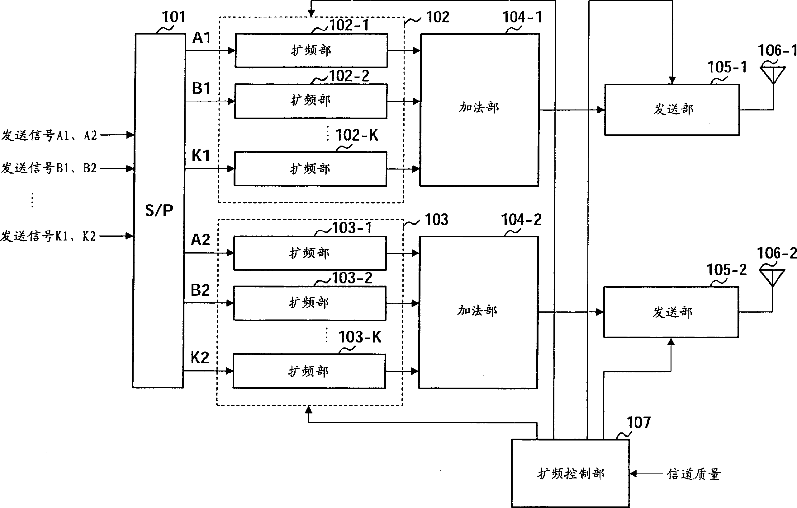
[0019] figure 1 It is a block diagram of the configuration of a CDMA transmitting apparatus according to Embodiment 1 of the present invention.
[0020] figure 1 The CDMA transmitting device of CDMA has a serial / parallel (S / P) conversion unit 101, spreading units 102 and 103, an adding unit 104, a transmitting unit 105, an antenna 106 and a spreading control unit 107. Among them, the spreading section 102 to the antenna 106-1 is the first transmission system, and the spreading section 103 to the antenna 106-2 is the second transmission system.
[0021] in figure 1 Among them, the transmission signals A1, A2, B1, B2, ... K1, K2 are composed of a plurality of substreams, and are input to the serial / parallel (S / P) conversion unit 101. Here, in these transmission signals, A1, B1, ... K1 represent data for the first transmission system, and A2, B2, ... K2 represent data for the second transmission system data. Moreover, the transmission signal has K seed streams, which are differe...
Embodiment 2
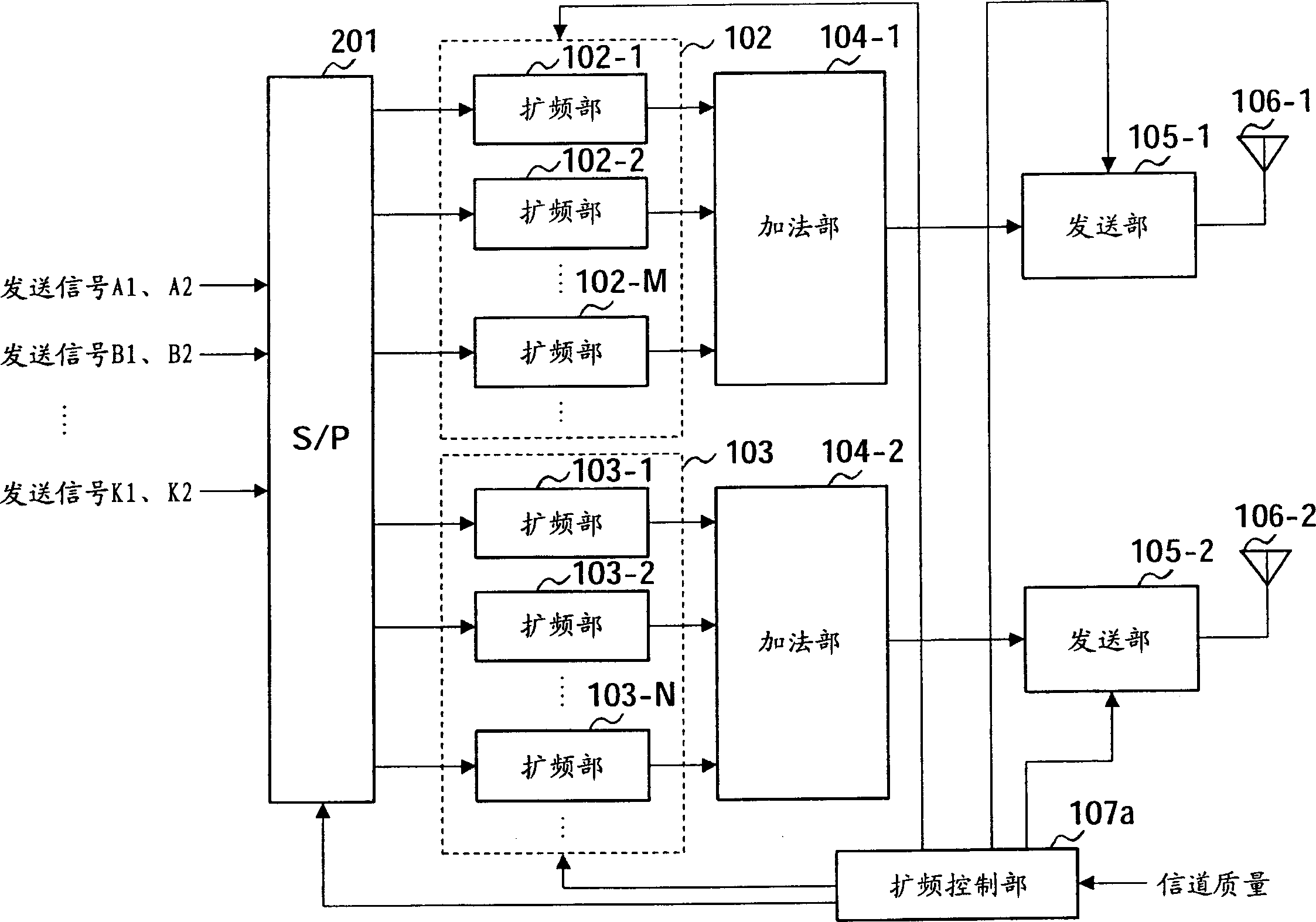
[0046] Attached image 3 It is a block diagram of the configuration of a CDMA transmitting apparatus according to Embodiment 2 of the present invention. This CDMA transmitter has and attached figure 1 The basic structure of the CDMA transmitter shown is the same as that of the attached figure 1 Attach and attach the same constituent elements in figure 1 The same reference numbers in the middle, and the corresponding description is omitted.
[0047] The feature of this embodiment is that the number of code multiplexing in the spreading method of each transmission system is changed according to the channel quality.
[0048] Attached image 3 , The spreading control section 107a determines the number of code multiplexing in the spreading sections 102 and 103 based on the notified channel quality, and outputs a control signal to the spreading sections 102 and 103 so that the spreading sections 102 and 103 use the determined Code multiplexing number to perform spread spectrum processi...
PUM
Abstract
An S / P converting section (101) converts input transmission signals A1, A2, B1, B2,..., K1,K2 to parallelized data, separated in individual transmission lines. Spreading sections (102,103) spread the respective data under control of a spread control section (107). Adding sections (104-1,104-2) multiplex spread data. Transmitting sections (105-1,105-2) provide radio transmission processing to the multiplexed signals, and transmit the data via antennas (106-1,106-2) by radio. The spread control section (107) controls the spreading methods in the spreading sections (102,103) based on channel quality. This makes it possible to improve error rate characteristics of the received signal and as maintain spectrum efficiency when varying data is transmitted from multiple antennas.
Description
Technical field [0001] The present invention relates to a transmitting device and a receiving device for performing parallel communication of different data between multiple transmitting and receiving antennas, such as MIMO (Multi Input / Multi Output) communication. Background technique [0002] In recent years, as a technology capable of supporting large-capacity data communications such as images, MIMO (Multi Input / Multi Output, Multiple Input Multiple Output) communication has received more and more attention. [0003] In MIMO communication, different transmission data (sub-streams) are sent from multiple antennas at the transmitting end, and at the receiving end, the propagation path estimation value is used to restore the multiple transmission data mixed in the propagation path to the original Send data (for example, Japanese Patent Laid-Open No. 2002-44051 (attached Figure 4 )). [0004] In fact, in MIMO communication, the signal transmitted from the transmitting device is ...
Claims
Application Information
Patent Timeline
Application Date:The date an application was filed.
Publication Date:The date a patent or application was officially published.
First Publication Date:The earliest publication date of a patent with the same application number.
Issue Date:Publication date of the patent grant document.
PCT Entry Date:The Entry date of PCT National Phase.
Estimated Expiry Date:The statutory expiry date of a patent right according to the Patent Law, and it is the longest term of protection that the patent right can achieve without the termination of the patent right due to other reasons(Term extension factor has been taken into account ).
Invalid Date:Actual expiry date is based on effective date or publication date of legal transaction data of invalid patent.

