Multicarrier transmitting apparatus, multicarrier receiving apparatus, and their methods

A transmitting device and multi-carrier technology, which is applied in the direction of modulated carrier system, multiplex communication, communication between multiple stations, etc., can solve the problems of deterioration of reception quality, reduction of data symbol error rate characteristics, etc., and achieve improvement Error rate characteristics, effect of improving reception quality

Inactive Publication Date: 2008-07-30
PANASONIC CORP
View PDF1 Cites 1 Cited by
  • Summary
  • Abstract
  • Description
  • Claims
  • Application Information

AI Technical Summary

Problems solved by technology

That is to say, there is a problem that since the effect of duplication does not appear in channel estimation using pilot symbols, if a channel estimation error occurs due to the influence of fading or the like, the error rate characteristics of the data symbols will also vary. The reduction, thereby deteriorating the quality of reception

Method used


Image

  • Multicarrier transmitting apparatus, multicarrier receiving apparatus, and their methods
  • Multicarrier transmitting apparatus, multicarrier receiving apparatus, and their methods
  • Multicarrier transmitting apparatus, multicarrier receiving apparatus, and their methods

Examples


Embodiment approach 1

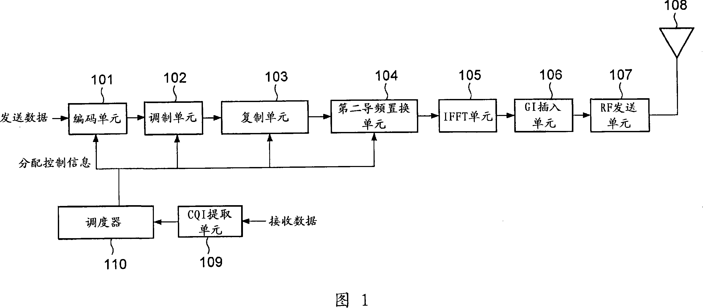
[0043] FIG. 1 is a block diagram showing the main configuration of a multicarrier transmission device according to Embodiment 1 of the present invention.

[0044] The multi-carrier transmission device in this embodiment includes: a coding unit 101, a modulation unit 102, a replication unit 103, a second pilot replacement unit 104, an IFFT (Inverse Fast Fourier Transform) unit 105, a GI (Guard Interval) insertion unit 106, an RF (Radio Frequency) transmitting unit 107 , transmitting antenna 108 , CQI (Channel Quality Indicator) extracting unit 109 and scheduler 110 .

[0045] Each part of the multicarrier transmission device according to this embodiment performs the following operations.

[0046] Encoding section 101 encodes transmission data such as voice, text document, and video based on the encoding rate instructed by scheduler 110 , and outputs the encoded signal to modulation section 102 . In addition, encoding section 101 also encodes allocation control information to b...

Embodiment approach 2

[0092] Since the multi-carrier transmitting apparatus according to Embodiment 2 of the present invention has the same basic configuration as the multi-carrier transmitting apparatus shown in Embodiment 1, its description is omitted, and the second pilot replacement unit 104 in Embodiment 1 will be described below. The second pilot replacement unit 204 with different structures will be described.

[0093] FIG. 11 is a block diagram showing the main configuration inside the second pilot replacement unit 204 . Note that the same components as those of second pilot replacement section 104 described in Embodiment 1 are denoted by the same reference numerals, and description thereof will be omitted.

[0094] The multi-carrier transmission device according to this embodiment includes an interleaving unit 241 in the second pilot replacement unit 204, thereby improving error tolerance against frequency selective fading and the like.

[0095] The interleaving unit 241 stores a pluralit...

Embodiment approach 3

[0113] The multi-carrier transmission device according to Embodiment 3 of the present invention interleaves a replica signal based on an interleave pattern determined in advance between the transmission device and the reception device, and then determines a replacement position for the second pilot. That is, since the interleaving pattern is not changed based on the replacement position, it is not necessary to separately notify the multicarrier receiving apparatus of the interleaving pattern as in the second embodiment.

[0114] That is, the multicarrier transmission device of this embodiment corresponds to a modification of the multicarrier transmission device described in Embodiment 2. Therefore, only the second pilot replacing section 204a which operates partly differently from the second pilot replacing section 204 described in Embodiment 2 will be described below.

[0115] Fig. 18 is a block diagram showing the main configuration inside the second pilot replacement unit 2...


PUM


Abstract

Disclosed is a multi-carrier transmission device capable of improving error rate characteristics of data symbols and thereby improving reception quality. In this device, a replacement position determining unit (141) determines which data symbols among a plurality of data symbols are to be replaced with the second pilot based on the number of replacements notified from the scheduler (110). Here, the constraint condition of (RF after replacement)≥(RF−1 before replacement) should be satisfied. The replacement unit (142) replaces a part of the data symbols included in the replica signal with the second pilot symbols based on the replacement position output from the replacement position determination unit (141), and outputs the obtained replacement signal to the IFFT unit (105).

Description

technical field [0001] The present invention relates to a multi-carrier transmission device, a multi-carrier reception device, a multi-carrier transmission method, and a multi-carrier reception method used in communication systems such as OFDM (Orthogonal Frequency Division Multiplex). Background technique [0002] In recent years, various kinds of information such as e-mails, documents, images, and voices have become objects of transmission, thereby increasing Internet traffic. Moreover, the demand for high-speed packet transmission technology in mobile communication is also increasing. However, when performing high-speed transmission in mobile communications, the influence of delayed waves due to multipath cannot be ignored, and the transmission characteristics deteriorate due to frequency selective fading. [0003] As one of the technologies for coping with frequency selective fading, multi-carrier communication represented by OFDM has attracted much attention. Multi-ca...

Claims


Application Information

Patent Timeline
Patent Type & Authority Applications(China)
IPC IPC(8): H04J11/00H04J1/02H04B7/26
CPCH04L1/0071H04L1/08H04L25/0226H04L27/261
Inventor 栗谦一三好宪一今村大地西尾昭彦福冈将星野正幸
Owner PANASONIC CORP
Why Eureka
Try Eureka