CDMA transmitting apparatus and CDMA receiving apparatus

a technology of cdma and receiving apparatus, which is applied in the direction of data switching networks, orthogonal multiplexes, multiplex communication, etc., can solve the problems of spectrum efficiency decline, poor propagation path characteristics, and error rate characteristics upon demodulation of received data, so as to maintain spectrum efficiency and improve the error rate characteristics of received data

Active Publication Date: 2010-04-06
INVT SPE LLC
View PDF32 Cites 3 Cited by
  • Summary
  • Abstract
  • Description
  • Claims
  • Application Information

AI Technical Summary

Benefits of technology

[0007]An object of the present invention is to provide a CDMA transmitting apparatus and a CDMA receiving apparatus that, when varying data is transmitted from multiple antennas, maintain the spectrum efficiency and improve the error rate characteristics of the received data.
[0011]Accordingly, for example, when the above spreading method changes the spreading factor in spreading for each transmission line, the spreading factor used in a transmission line with poor channel quality (transmission path environment) is increased, thereby making it possible to improve the channel quality. Moreover, important data is transmitted through a transmission line with a high spreading factor, thereby making it possible to improve error rate characteristics of important data.

Problems solved by technology

The propagation path environment where carrier waves transmitted from the multiple antennas of the MIMO transmitting apparatus pass is not equal, and there are propagation paths with poor propagation path characteristics.
In such case, at time of compensating other channel interference, an interference compensation error occurs in data transmitted through the propagation path due to noise and the like, and error rate characteristics upon demodulation of the received data decrease.
However, in order to improve the error rate characteristic, if transmission power is increased, if a spreading factor is increased, or if the number of code division multiplexes is decreased in the case of using a CDMA system, the spectrum efficiency also decrease, leading to an unfavorable result that a channel capacity is reduced in view of the entire system.

Method used


Image

  • CDMA transmitting apparatus and CDMA receiving apparatus
  • CDMA transmitting apparatus and CDMA receiving apparatus
  • CDMA transmitting apparatus and CDMA receiving apparatus

Examples


embodiment 1

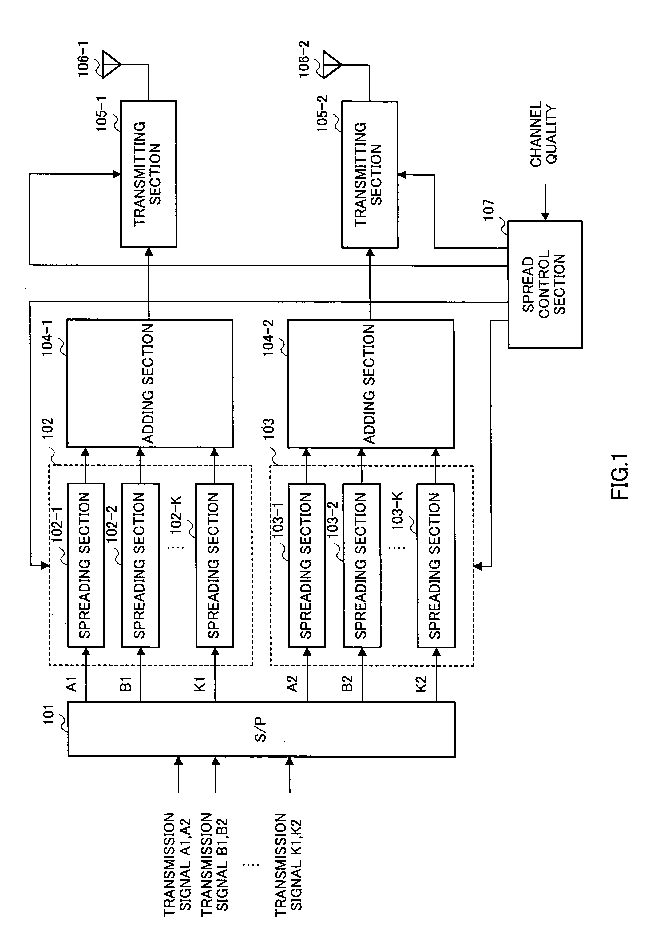
[0019]FIG. 1 is a block diagram illustrating a configuration of a CDMA transmitting apparatus according to Embodiment 1 of the present invention.

[0020]The CDMA transmitting apparatus illustrated in FIG. 1 has an S / P converting section 101, spreading sections 102, 103, an adding section 104, a transmitting section 105, an antenna 106, and a spread control section 107. Among these, the spreading section 102 to the antenna 106-1 will be referred to as a first transmission line, and the spreading section 103 to the antenna 106-2 will be referred to as a second transmission line.

[0021]In FIG. 1, transmission signals A1, A2, B1, B2, . . . , K1, K2, each having multiple sub-streams, are input to the S / P converting section 101. Here, among these transmission signals, A1, B1, . . . , K1 represent the data for the first transmission line and A2, B2, K2 represent the data for the second transmission line. Moreover, the transmission signals have K types of sub-streams. For example, sub-streams ...

embodiment 2

[0045]FIG. 3 is a block diagram illustrating a configuration of a CDMA transmitting apparatus according to Embodiment 2 of the present invention. This CDMA transmitting apparatus has the same basic configuration as that of the CDMA transmitting apparatus shown in FIG. 1, and the same reference characters as those of FIG. 1 are added to the same configuration components as those of FIG. 1, and the explanation is omitted.

[0046]A feature of this embodiment is that, among spreading methods for each transmission line, the number of code multiplexes changes based on the channel qualities.

[0047]In FIG. 3, a spread control section 107a decides the number of code multiplexes in the spreading sections 102 and 103 based on the notified channel qualities, and outputs a control signal to the spreading sections 102 and 103 so that the spreading sections 102 and 103 perform spread processing using the decided number of code multiplexes. Moreover, a control signal is also output to an S / P convertin...


PUM


Abstract

An S / P converting section (101) converts input transmission signals A1, A2, B1, B2, . . . , K1, K2 to parallelized data, separated in individual transmission lines. Spreading sections (102, 103) spread the respective data under control of a spread control section (107). Adding sections (104-1, 104-2) multiplex spread data. Transmitting sections (105-1, 105-2) provide radio transmission processing to the multiplexed signals, and transmit the data via antennas (106-1, 106-2) by radio. The spread control section (107) controls the spreading methods in the spreading sections (102, 103) based on channel quality. This makes it possible to improve error rate characteristics of the received signal and as maintain spectrum efficiency when varying data is transmitted from multiple antennas.

Description

TECHNICAL FIELD[0001]The present invention relates to a transmitting apparatus and a receiving apparatus that perform parallel communication of varying data between multiple transmission and reception antennas, as in MIMO (Multi-Input / Multi-Output) communications.BACKGROUND ART[0002]In recent years, attention has been paid to MIMO (Multi-Input / Multi-Output) communications as a technique that enables communications for large-capacity data such as image.[0003]In MIMO communications, varying transmission data (sub-streams) is transmitted from multiple antennas at the transmitting side, and the receiving side separates the multiple transmission data mixed through the propagation path back to the original transmission data using propagation path estimation values (for example, see Unexamined Japanese Patent Publication No. 2002-44051 (FIG. 4)).[0004]Actually, in MIMO communications, signals sent from transmitting apparatuses are received by the same or a greater number of antennas than t...

Claims


Application Information

Patent Timeline
Patent Type & Authority Patents(United States)
IPC IPC(8): H04B7/216H04B7/04H04B7/06H04J99/00H04B7/08H04J11/00H04J13/00H04J13/16H04L1/00H04L1/18
CPCH04L1/0003H04B2201/70703H04L1/18
Inventor SUDO, HIROAKI
Owner INVT SPE LLC
Why Eureka
Try Eureka