Spray gun

A technology of spray gun and atomizing nozzle, applied in the field of spray gun

Active Publication Date: 2012-01-25
J WAGNER GMBH
View PDF5 Cites 0 Cited by
  • Summary
  • Abstract
  • Description
  • Claims
  • Application Information

AI Technical Summary

Problems solved by technology

But the main drawback is that the level of noise generated by the high-speed rotating air turbine is not sufficiently attenuated only by the components housing the electric drive motor
Therefore, the spray gun cannot be proven to be effective in actual use

Method used


Image

  • Spray gun
  • Spray gun
  • Spray gun

Examples


Embodiment Construction

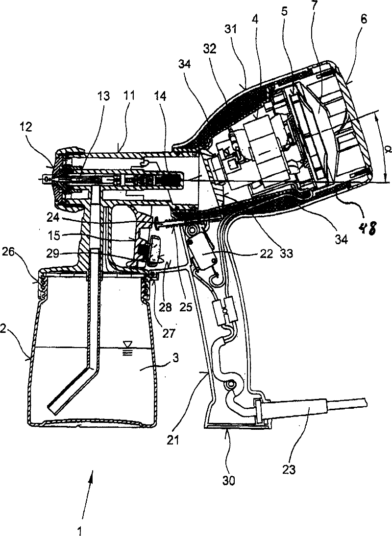
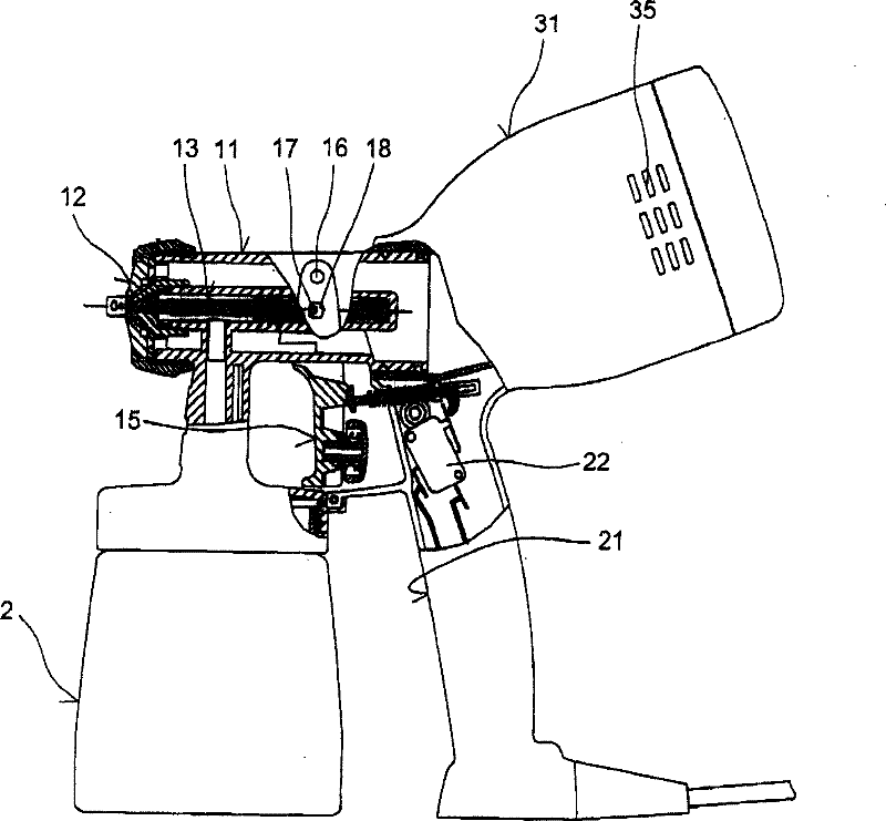
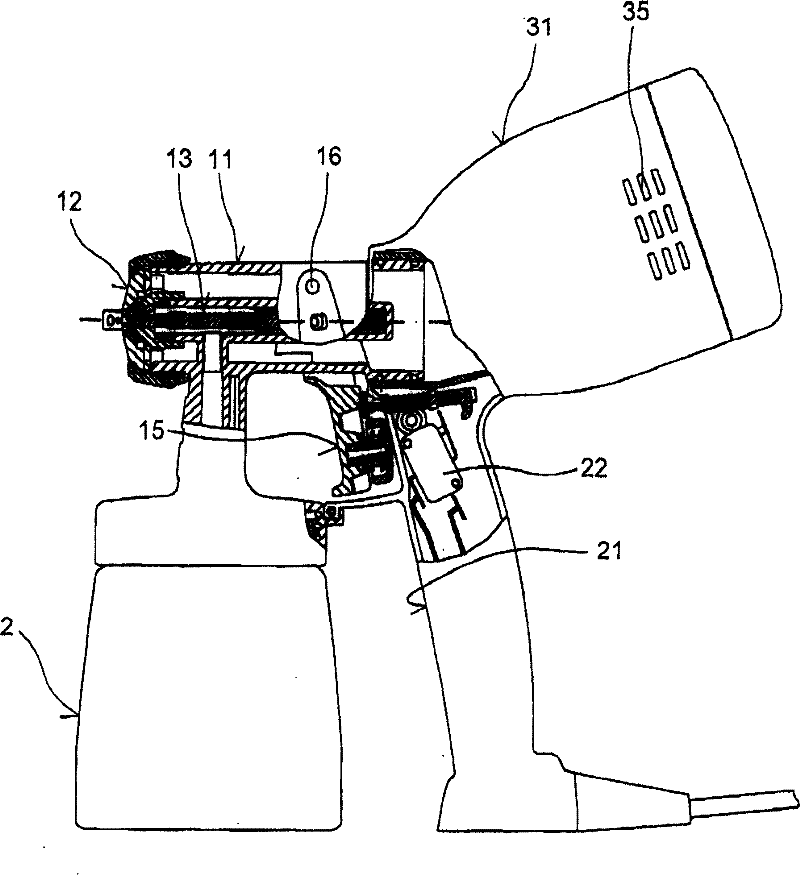
[0036] figure 1 , 2 , 3 and 4 and denoted as 1 or 1' are used to atomize paint, varnish or similar medium 3 located in storage container 2, which can be supplied to the workpiece by air flow. In the illustrated embodiment, the air flow for atomization is formed by an air turbine 5 which may be driven by an electric drive motor 4 . In addition, the air turbine 5 is provided with a muffler 6 in order to reduce input noise, while a cavity 7 is formed between the muffler 6 and the air turbine 5 for the same purpose.

[0037] The spray gun 1 mainly includes a sleeve 11 connected with a storage container 2, an atomizing nozzle 12 equipped with an axially adjustable nozzle needle 13 and connected to the sleeve 11, a handle 21, and an accessory 31 formed on the handle 21. In the case of the gun 1 , the attachment 31 is firmly connected to the sleeve and houses the air turbine 5 , its electric drive motor 4 and the muffler 6 . The spray gun can be driven by a lever 15 operated agains...


PUM


Abstract

In a spray gun (1) for atomizing fluids, that can be actuated using a lever (15) mounted in a pivoting arrangement on a sleeve (11) which accommodates an atomizer nozzle (12) and in which the air flow can be generated by an air turbine (5) that is assigned to the spray gun (1), the air turbine (5) and its electric drive motor (4) are arranged substantially coaxially to the atomizer nozzle (12) amounting the sleeve (11) on the side of a handle (21) opposite to the sleeve (11) of the atomizer nozzle (12) and the air flow is supplied from the air turbine (5) in a straight line or a substantiallystraight line through the sleeve (11) of the atomizer nozzle (12). The air turbine (5) is provided with a muffler (6).

Description

technical field [0001] The present invention relates to a spray gun capable of atomizing paint, varnish or similar medium supplied by an air stream to a workpiece, wherein the spray gun can be activated by means of a lever mounted in a pivoting arrangement on a sleeve housing the atomizing nozzle, And the air flow can be generated by an air turbine corresponding to the spray gun. Background technique [0002] A spray gun of this type is disclosed in FR8014566. In this embodiment, the electric drive motor driving the air turbine can be disassembled together with the air turbine and arranged on a separate part on the housing of the spray gun perpendicular to the atomizing nozzle of the spray gun, so that the air flow generated by the air turbine is Change direction several times before the atomizing nozzle flows out. [0003] This creates significant flow noise as well as flow losses, so the spray gun does not provide an acceptable level of efficiency. Another drawback is t...

Claims


Application Information

Patent Timeline
Patent Type & Authority Patents(China)
IPC IPC(8): B05B7/02B05B15/00B05B7/24
CPCB05B7/2416
Inventor A·格林P·伊贝勒A·克雷默J·乌尔布里希
Owner J WAGNER GMBH
Why Eureka
Try Eureka