Drying system of film developing machine

A drying system, processor technology, applied in drying/glazing processing materials, etc., can solve problems such as loss, fire, damage to film parts, etc.

Inactive Publication Date: 2006-01-04
SHANGHAI SHENBEI OFFICE MASCH CO LTD
View PDF0 Cites 2 Cited by
  • Summary
  • Abstract
  • Description
  • Claims
  • Application Information

AI Technical Summary

Problems solved by technology

Especially when the blower fails, due to the continuous heating of the heating element, it ...

Method used


Image

  • Drying system of film developing machine

Examples


Embodiment Construction

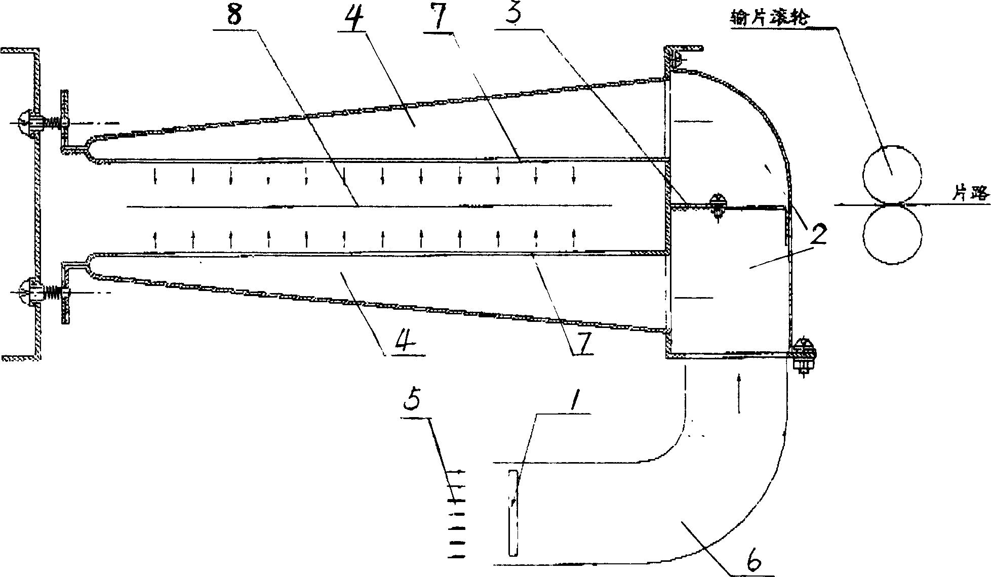
[0009] by figure 1 It is the best embodiment of the present invention.

[0010] The main components of the film processor drying system are fan 5, PTC drying ceramic heating element 1, air duct 6, hot air box 2, air volume adjustment plate 3, and tapered air duct 4. The PTC dry ceramic heating element 1 is installed in an appropriate position of the air duct 6, and the air duct 6 is sealed and connected with the hot air box 2. The hot air box 2 is divided into upper and lower parts of the box, and the air volume regulating plate 3 in the hot air box 2 can adjust the air volume of the upper and lower boxes of the hot air box, so that the air volume of the upper and lower box air outlets of the hot air box 2 is even. The large openings of the upper and lower tapered air ducts 4 are respectively connected to the upper and lower hot air box 2 air outlets, and the other end is fixed on the wallboard. When the fan 5 works, the wind blows to the PCT ceramic heating element 1, causi...


PUM


Abstract

The present invention relates to one drying system to dry film homogeneously inside one conic air duct by means of the heat effect of heating PTC ceramic element. The drying system consists of blower, air duct, heating element, hot blast tank and air pipes. The blower blows blast via air duct to the heating PTC ceramic element via air duct to generate heat effect. Hot blast entering the hot blast tank from the air duct is divided into two parts to enter separately to the upper and the lower conic air pipes from their large ports and the two parts, after passing through the conic surface of the air pipes, blow to the films through the air outlet slits. The present invention has no damage of film and the peripheral parts owing to the conic air pipes to make the films to obtain homogeneous wind and heat.

Description

Technical field [0001] The invention relates to a drying system of a film developing machine, in particular to a device in which the thermal effect of a heating element passes through a conical air duct to evenly dry a film. Background technique [0002] In the past, the drying structures in the drying system of film processors were mostly infrared heating, hot air drying, electric heating wire heating, hot air drying, etc. The heating elements of these two structures are different, the former is an infrared heating tube, and the latter is heated by an electric heating wire. But the drying principle is the same, and the blower blows the hot air to the film through the heating element to achieve the drying effect. The disadvantage is that the wind and heat are not very uniform, and the film drying effect is not good. Sometimes wind-drying marks appear on the surface of the film. Especially when the blower fails, due to the continuous heating of the heating element, it will...

Claims


Application Information

Patent Timeline
IPC IPC(8): G03D15/02
Inventor 张竹君陈长玉
Owner SHANGHAI SHENBEI OFFICE MASCH CO LTD
Why Eureka
Try Eureka