Automobile underbody structure

A vehicle body and bending technology, which is applied in the field of the lower structure of the vehicle body, can solve the problems of the disclosure of the technical significance of the frame without the bottom plate, etc.

Inactive Publication Date: 2006-03-29
MAZDA MOTOR CORP
View PDF1 Cites 10 Cited by
  • Summary
  • Abstract
  • Description
  • Claims
  • Application Information

AI Technical Summary

Problems solved by technology

Patent Document 1 (Japanese Patent Laid-Open Publication No. Hei 11-78959) discloses a structure in which a pair of left and right floor frames are tilted so as to gradually move toward the inside in the vehicle width direction as they extend rearward. directly related, so no disclosure was made on the technical significance of the above-mentioned inclination of the floor frame

Method used


Image

  • Automobile underbody structure
  • Automobile underbody structure
  • Automobile underbody structure

Examples


Embodiment Construction

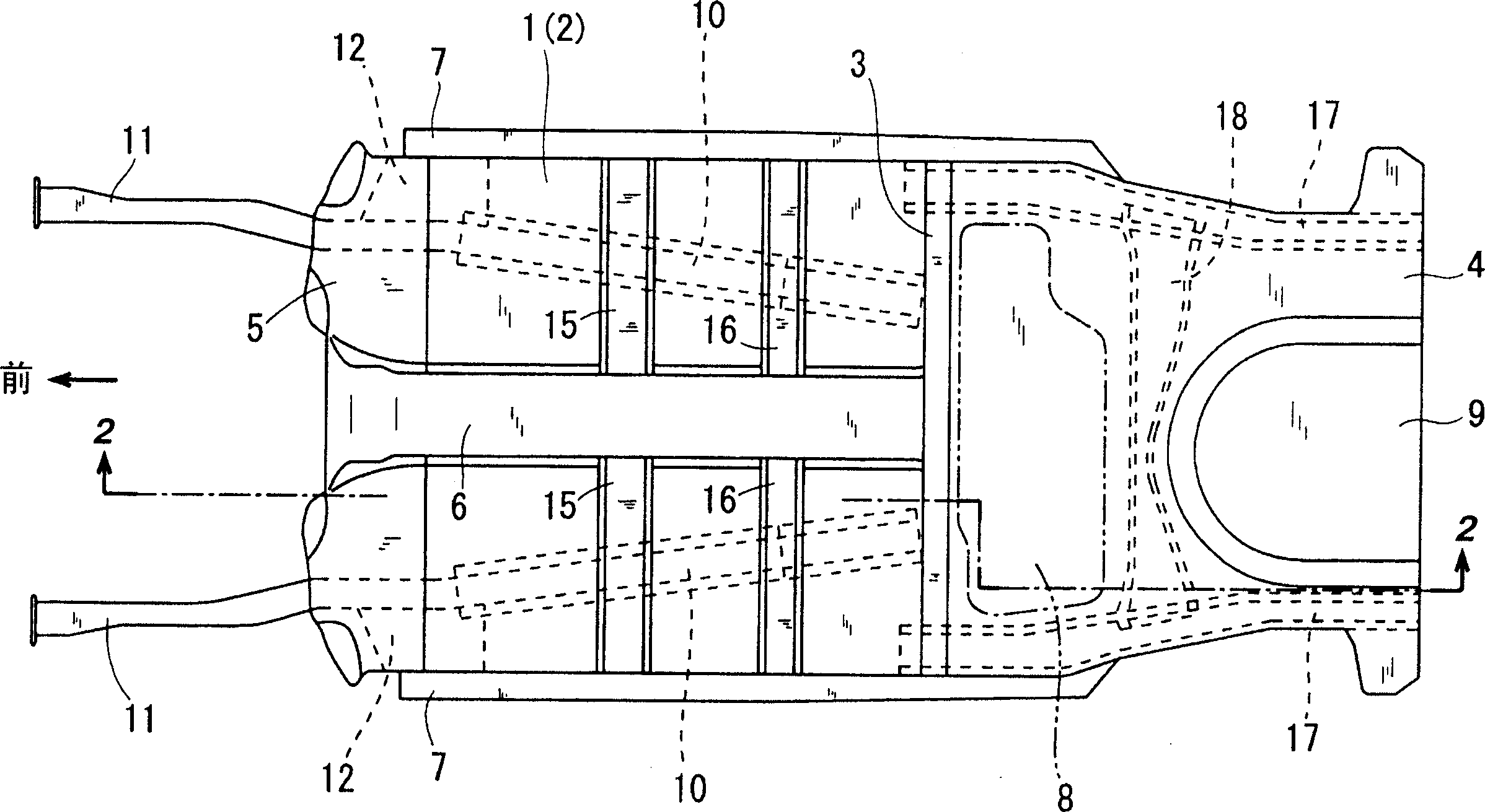
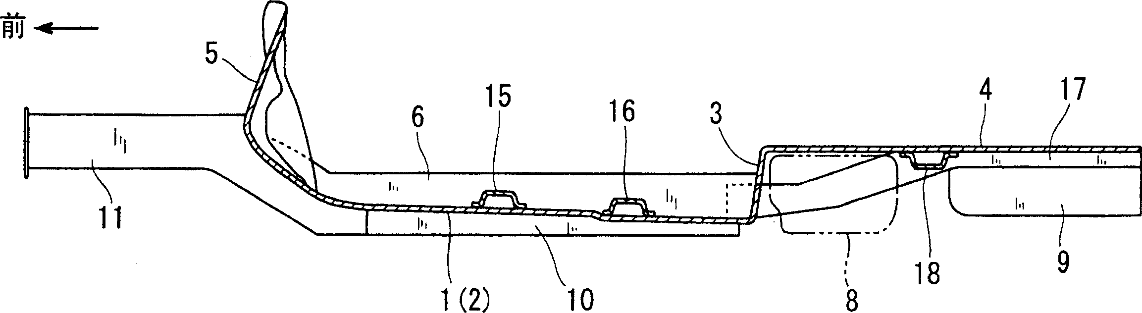
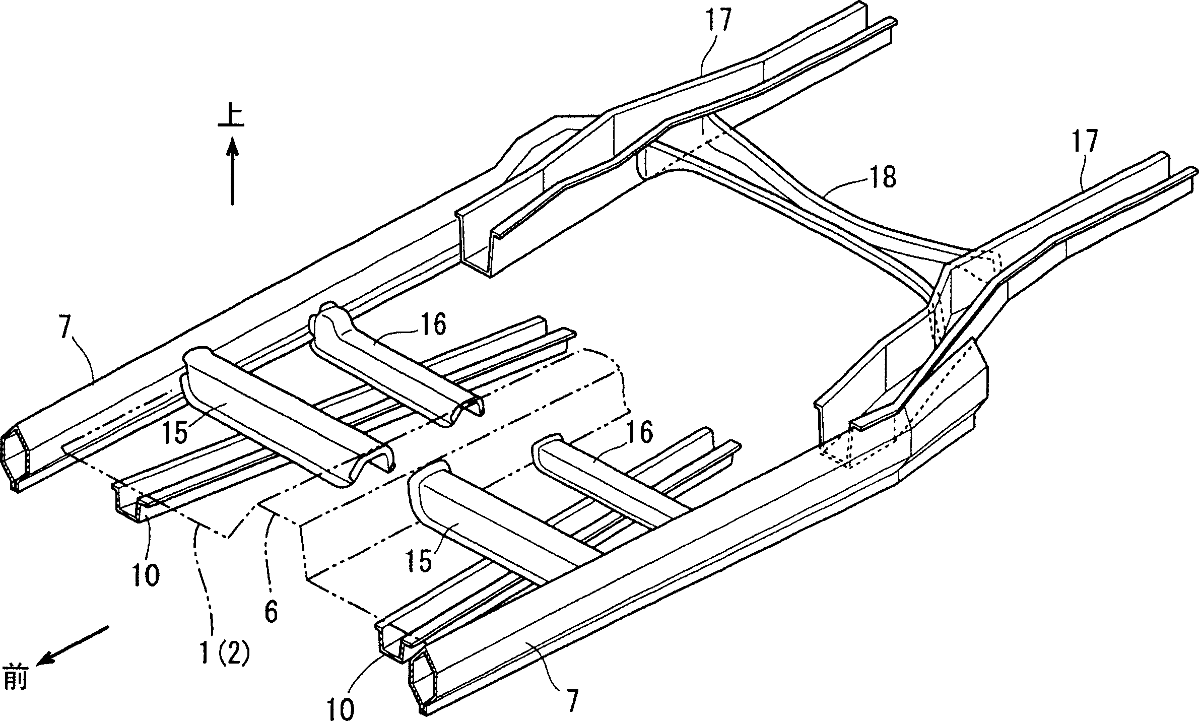
[0058] figure 1 , figure 2 Among them, 1 is the bottom plate, which is formed by jointing a plurality of panel materials divided and formed along the front-rear direction. The bottom plate 1 generally includes a front bottom plate portion 2; a rear upward curved portion 3 that rises shortly upward from the rear end of the front bottom plate portion 2, and a rear bottom plate portion 4 that extends rearward from the upper end of the rear upward curved portion 3. . The front end of the front floor portion 2 extends in the vertical direction, and is connected to the lower end of a partition 5 that partitions the vehicle compartment and the engine compartment.

[0059] The front floor part 2 is formed with a channel part 6 extending in the front-rear direction at the central part in the vehicle width direction. connected (opening to the rear). The left and right end portions of the front floor portion 2 are joined to a pair of left and right side beams 7 as strength members e...


PUM


Abstract

Disclosed is an automobile underbody structure, wherein a pair of laterally-spaced floor frames 10 are disposed to extend longitudinally in such a manner as to interpose a tunnel region 6 of a front floor portion 2 therebetween and joined to a bottom surface of the front floor portion 2, and a cross member 15, 16 is disposed to extend laterally so as to connect each side-sill 7 and the tunnel region 6 and joined to a top surface of the front floor portion 2. Each of the floor frames 10 is gradually inclined laterally inward toward the rear end thereof so as to be obliquely disposed relative to the cross member 15, 16 in top plan view. A rearward displacement of the floor frames 10 during a head-on collision exerts a compressive force on a region of the cross member 15, 16 located on the laterally outward side relative to each of the floor frames 10, and a tensile force on a region of the cross member 15, 16 located on the laterally inward side relative to each of the floor frames 10. The automobile underbody structure of the present invention makes it possible to effectively receive a shock during a head-on collision by the cross member.

Description

technical field [0001] The present invention relates to a vehicle body substructure. Background technique [0002] Regarding the vehicle body of an automobile, its floor includes a front floor portion having a pair of left and right side beams connected and a tunnel portion (Tunnel portion) extending in the front-rear direction at the central part in the vehicle width direction; from the rear of the front floor portion a rear upwardly curved portion extending upward; and a rear floor portion extending substantially linearly rearward from the upper end of the rear upwardly curved portion. Generally, a pair of left and right floor frames extending in the front-rear direction and sandwiching the tunnel portion are joined to the bottom surface of the front floor portion, and the side beams and the tunnel portion are joined to the upper surface of the front floor portion. And a beam extending along the width of the vehicle. [0003] A pair of...

Claims


Application Information

Patent Timeline
Patent Type & Authority Applications(China)
IPC IPC(8): B62D25/20B62D23/00B62D21/15
Inventor 冈那文夫向山则孝岛田幸一郎森茂之
Owner MAZDA MOTOR CORP
Why Eureka
Try Eureka