vacuum cleaner mouth

A technology for vacuum cleaners and suction ports, which is applied in the direction of vacuum cleaners, suction nozzles, cleaning equipment, etc., can solve the problems that the inclination position of the vacuum cleaner nozzle cannot be effectively compensated, and achieve the effect of saving space, large vertical stroke, and realizing vertical stroke

Active Publication Date: 2016-07-13
威赛有限公司
View PDF9 Cites 0 Cited by
  • Summary
  • Abstract
  • Description
  • Claims
  • Application Information

AI Technical Summary

Problems solved by technology

This structure causes the floor slide to tip over slightly by friction on the floor covering during the movement of the cleaner nozzle and is not always optimally directed against the floor surface
In particular, the known structure of the floor slide cannot effectively compensate for an unintended tilted position of the vacuum cleaner nozzle when vacuuming

Method used


Image

  • vacuum cleaner mouth
  • vacuum cleaner mouth
  • vacuum cleaner mouth

Examples


Embodiment Construction

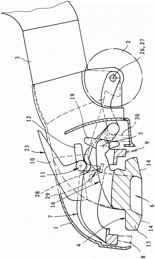
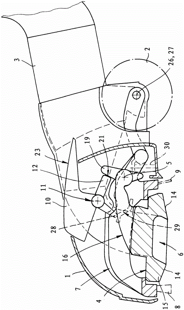
[0016] exist figure 1 with figure 2 The basic structure of the vacuum cleaner nozzle shown in includes a housing 1 supported on the rear side on at least one roller 2, a vertically deflectable connecting plate 3 for connecting the suction pipe and a floor slide 4, which slides The part is supported tiltably in the housing 1 about a pivot axis 5 and has a suction opening 6 . Furthermore, a carrier 7 is provided, on the underside of which at least one brush strip 8 and / or at least one sealing lip 9 are arranged. The carrier 7 is pivotally mounted in the housing 1 and is connected to a switch element 10 in a figure 1 shows the location of the carpet floor and a figure 2 Adjustable between smooth floor positions shown.

[0017] In the carpeted floor position, the frame 7 is raised and neither the brush strip 8 arranged on the underside of the frame 7 nor the sealing lip 9 likewise arranged on the bottom side of the frame 7 touch the floor. The vacuum cleaner nozzle is suppo...


PUM


Abstract

The invention relates to a vacuum cleaner nozzle, in particular for household vacuum cleaners, which has a floor runner which is mounted so as to be tiltable and which has a sliding surface on its underside for placement on a fabric floor and a suction port. The floor slide is formed as a rocker, the pivot axis of which is arranged behind the suction opening in the working direction. According to the invention, the floor runner (4) has a main body (15) open on the bottom, which has an outlet (13) on Sliding surface (14) on the surface. A laterally projecting arm (16) with a cylindrical bearing surface is provided on the main body (15) for pivotably mounting the floor runner (4).

Description

technical field [0001] The invention relates to a vacuum cleaner nozzle, in particular for household vacuum cleaners, which has a floor runner which is mounted so as to be tiltable and which has a sliding surface on its underside for placing on a fabric floor and a suction port. Background technique [0002] A vacuum cleaner nozzle of the character described is known from DE 197 38 046 A1. The pivot axis of the floor runner runs centrally opposite the suction opening and in a channel of the floor runner that forms the suction opening. During the oscillating movement of the floor slide, a reverse vertical movement is made towards the suction opening bordering the suction opening edge. This construction leads to the fact that the floor runner tilts slightly due to friction on the floor covering during the movement of the cleaner nozzle and does not always lie optimally against the floor surface. In particular, the known design of the floor slide cannot effectively compensat...

Claims


Application Information

Patent Timeline
Patent Type & Authority Patents(China)
IPC IPC(8): A47L9/02
CPCA47L9/0653
Inventor H·迪尔格M·齐德克H-J·施托伊特纳
Owner 威赛有限公司
Why Eureka
Try Eureka