an automatic lifting mechanism

An automatic lifting and lifting plate technology, applied in the direction of lifting devices, etc., can solve the problems of inability to realize the full height of the indoor clear height, the inability to guarantee the straightness of the lifting trajectory, and the lack of high-precision controllable movement, etc., to improve the anti-overturning ability, The effect of large vertical stroke and large load capacity

Active Publication Date: 2022-02-11
上海蔚建科技有限公司
View PDF16 Cites 0 Cited by
  • Summary
  • Abstract
  • Description
  • Claims
  • Application Information

AI Technical Summary

Problems solved by technology

[0002] At present, there are many mechanisms that can be used for indoor lifting, but basically they can only achieve a partial height increase, and cannot achieve the full height increase of the indoor net height. While the object is lifted in the vertical direction, there is no high-precision controllable movement of other degrees of freedom
In addition, when the existing lifting mechanism has a large load, the lifting mechanism itself has a large deformation, which cannot guarantee the straightness of the trajectory during the lifting process.

Method used


Image

  • an automatic lifting mechanism
  • an automatic lifting mechanism
  • an automatic lifting mechanism

Examples


Embodiment Construction

[0046] The present invention will be described in detail below in conjunction with specific embodiments. The following examples will help those skilled in the art to further understand the present invention, but do not limit the present invention in any form. It should be noted that those skilled in the art can make several modifications and improvements without departing from the concept of the present invention. These all belong to the protection scope of the present invention.

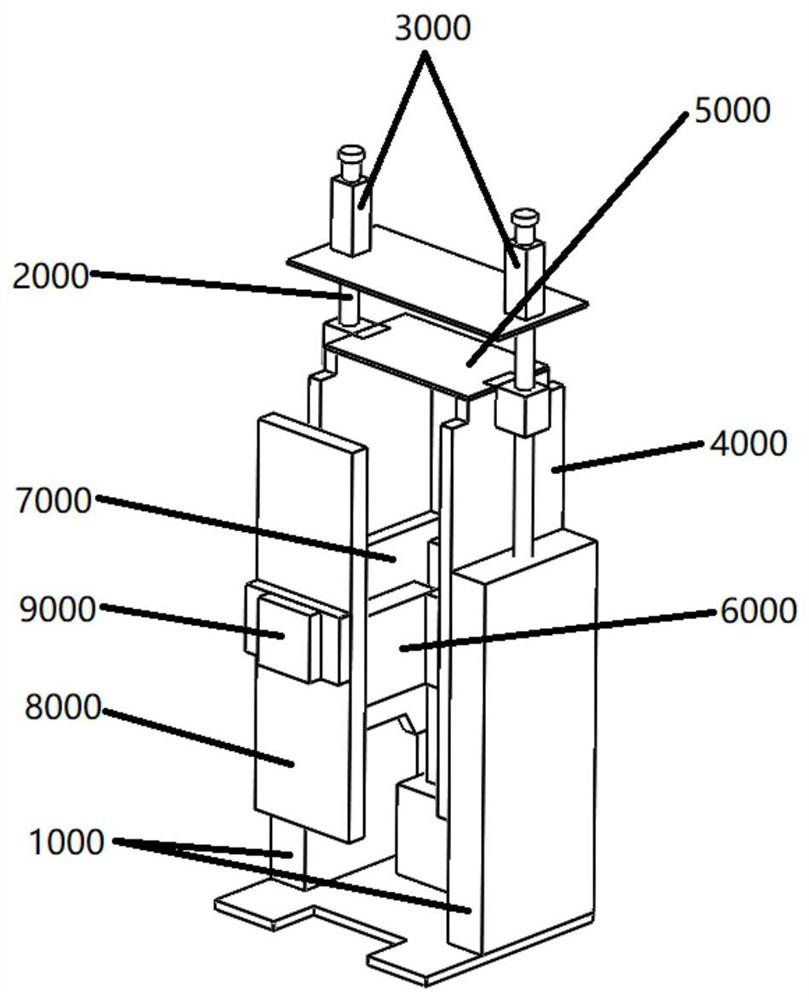
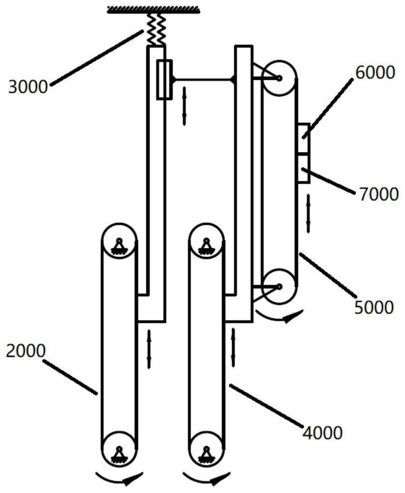
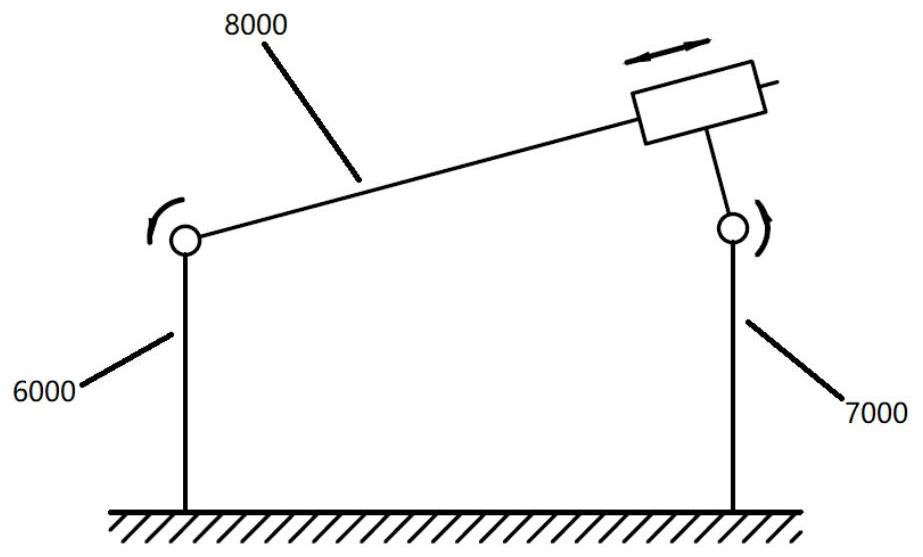
[0047] refer to figure 1As shown, it is a structural schematic diagram of an automatic lifting mechanism in a preferred embodiment of the present invention. The automatic lifting mechanism is mainly used for indoor automatic lifting equipment with heavy loads from the ground to the full height of the ceiling. The figure includes a frame 1000, a first-level lifting Device 2000 , second stage lifting device 4000 , third stage lifting device 5000 , left arm 6000 , right arm 7000 , fourth stage liftin...


PUM


Abstract

The present invention provides an automatic lifting mechanism, comprising: a first-level lifting device capable of lifting and lowering along the vertical direction, and capable of propping up on the ceiling; a second-level lifting device arranged on the frame, Lifting movement, and its upper end is connected with the first-level lifting device through a sliding pair to improve its own rigidity; the third-level lifting device performs synchronous lifting movement with the second-level lifting device; the left 1. The right arm moves up and down synchronously with the third-level lifting device, and respectively performs forward and backward telescopic movements along the vertical direction of the third-level lifting device; the fourth-level lifting device performs synchronous telescopic movement with the left arm and / or right arm Movement and angle adjustment, lifting movement along the vertical direction; lateral movement device performs synchronous telescopic movement and / or lifting movement with the fourth-level lifting device. The invention has high precision, high rigidity, large bearing capacity and high degree of freedom, and simultaneously realizes multi-degree-of-freedom and high-precision controllable motion in other directions.

Description

technical field [0001] The invention relates to the field of automatic lifting and lowering of loads, in particular to an automatic lifting mechanism for heavy loads that is mainly used indoors from the ground to the full height of the ceiling. Background technique [0002] At present, there are many mechanisms that can be used for indoor lifting, but basically they can only achieve a partial height increase, and cannot achieve the full height increase of the indoor net height. While the object is lifted in the vertical direction, there is no high-precision controllable movement of other degrees of freedom. In addition, when the load of the existing lifting mechanism is large, the lifting mechanism itself has a large deformation, and the straightness of the trajectory during the lifting process cannot be guaranteed. Contents of the invention [0003] Aiming at the defects in the prior art, the object of the present invention is to provide an automatic lifting mechanism. ...

Claims


Application Information

Patent Timeline
Patent Type & Authority Patents(China)
IPC IPC(8): B66F11/00B66F13/00
CPCB66F11/00B66F13/00
Inventor 童飞梁衍学
Owner 上海蔚建科技有限公司
Why Eureka
Try Eureka