Installation structure of sound insulation wall in railway vehicle engine room

A technology for rail vehicles and installation structures, applied in railway car body, transportation and packaging, railway car body parts, etc. Good sound insulation and torsion resistance

Active Publication Date: 2016-06-08
CRRC NANJING PUZHEN CO LTD
View PDF5 Cites 0 Cited by
  • Summary
  • Abstract
  • Description
  • Claims
  • Application Information

AI Technical Summary

Problems solved by technology

The roof and side walls are assembled as two separate parts. When the whole vehicle is assembled, it is difficult to align the roof curved beams and side wall columns, and the process is not easy to guarantee; intensive spot welding is adopted with the side wall columns and roof curved beams, and the sound insulation wall The lower beam directly falls on the vertical plate where the corrugated floor of the chassis is docked, and the beam is only welded to the wave crest of the corrugated floor, so the sound insulation effect of the sound insulation wall is poor

Method used


Image

  • Installation structure of sound insulation wall in railway vehicle engine room
  • Installation structure of sound insulation wall in railway vehicle engine room
  • Installation structure of sound insulation wall in railway vehicle engine room

Examples


Embodiment Construction

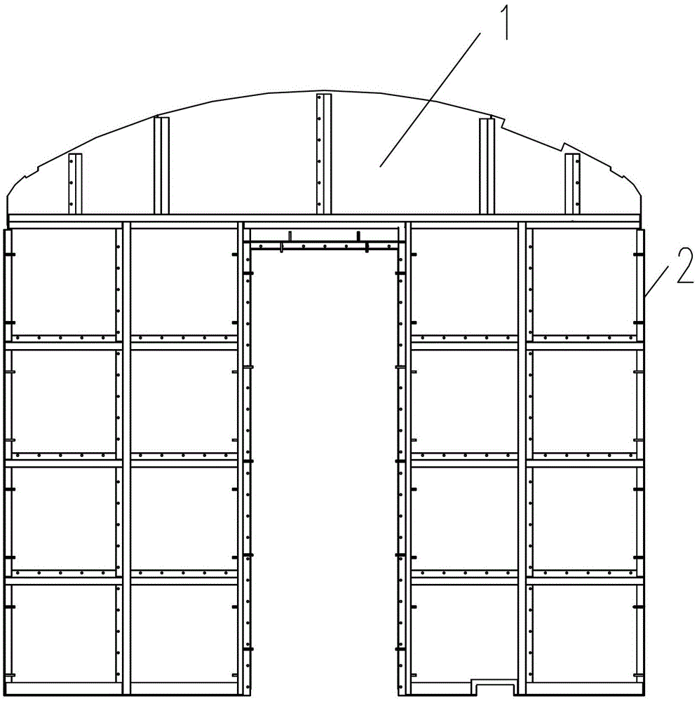
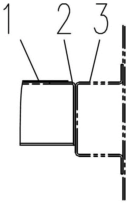
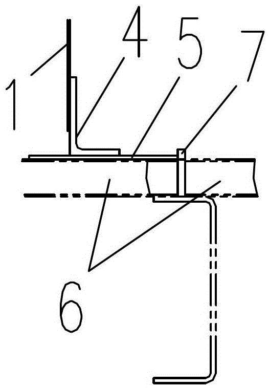
[0015] Such as figure 1 , figure 2 , image 3 As shown, the installation structure of the sound insulation wall of the rail vehicle machine room in this embodiment, the two sides of the sound insulation wall 1 are fully welded and connected with corner columns 2, and the corner column 2 in this example adopts an angle iron with a section of 3X35X85mm, and the outer surface of the corner column 2 One side of the facade is fully welded to the side wall column 3, and the other side is connected to the side wall column 3 by section welding or intensive spot welding; the lower beam 4 of the sound insulation wall is fully welded and connected with a patch 5, and the size of the patch is 2X120X3000mm, one side of the patch 5 is fully welded to the butt vertical plate 7 between the corrugated floor 6, and the other side of the patch 5 is welded to the crest of the corrugated floor 6; the upper end of the sound insulation wall 1 is fully welded to the 8 roof curved beams Solder conn...


PUM


Abstract

The invention relates to an engine room soundproof wall mounting structure for a railway vehicle. Angle-form vertical columns are connected to two sides of a soundproof wall by means of full-length welding. One side of the outer vertical face of each angle-form vertical column is connected with a side wall vertical column by means of full-length welding, and the other side of the outer vertical face of each angle-form vertical column is connected with the side wall vertical column through segment welding or dense point welding. A reinforcement plate is connected below a lower crossbeam of the soundproof wall by means of full-length welding. One side of the reinforcement plate is connected with a butt joint vertical plate between corrugated floors by means of full-length welding. The upper end of the soundproof wall is connected with a vehicle-top bent beam by means of full-length welding. By the two angle-form vertical columns added on two sides of the soundproof wall, torsion-resistant performance of the soundproof wall is increased, the position of the soundproof wall can be adjusted conveniently during assembling, and assembling difficulty of the soundproof wall is lowered. By the structure that the added angle-form vertical columns are connected with partition plates and side wall vertical columns by means of full-length welding, the reinforcement plate is welded at the butt joint position of the corrugated floors of a base frame and connected with the butt joint vertical plate by means of full-length welding, the lower crossbeam of the soundproof wall is connected with the reinforcement plate by means of full-length welding, and the soundproof wall is connected with a vehicle top by means of full-length welding, soundproof performance of the soundproof wall is increased.

Description

technical field [0001] The invention relates to a sound insulation wall installation structure for a rail vehicle machine room, and belongs to the technical field of rail vehicle body structure design. Background technique [0002] The sound insulation wall of the machine room is located between the engine room of the generator car and the power distribution room. The unit in the machine room is very noisy when it is working. There is only a sound insulation wall between the staff and the sound insulation wall. The sound insulation wall is not well sealed, and the noise will directly affect the power distribution. Therefore, the sealing performance of the sound insulation wall is very important. In the past, the sound insulation wall of the generator room has openings on both sides of the skeleton, no columns, and the skeleton does not form a frame. The rigidity is poor during hoisting, and it is easy to twist and deform. During assembly, the partition wall panels, side wal...

Claims


Application Information

Patent Timeline
Patent Type & Authority Patents(China)
IPC IPC(8): B61D17/06
Inventor 施青松杜彦品朱亮陈海俊廖平李康王卫
Owner CRRC NANJING PUZHEN CO LTD
Why Eureka
Try Eureka