Bone conduction device

A technology of bone conduction and bone conduction speakers, which is applied in the direction of bone conduction transducer hearing equipment, damping device of diaphragm, sensor, etc., which can solve the problems of volume sense damage and insufficient air vibration

Inactive Publication Date: 2006-04-12
TEMCO JAPAN
View PDF0 Cites 10 Cited by
  • Summary
  • Abstract
  • Description
  • Claims
  • Application Information

AI Technical Summary

Problems solved by technology

However, when such a method of use is adopted, sufficient air vibration cannot be obtained, and there is a problem that the volume perception is impaired.

Method used


Image

  • Bone conduction device
  • Bone conduction device
  • Bone conduction device

Examples


Embodiment Construction

[0014] Embodiments of the present invention will be described with reference to the drawings. Although the bone conduction device of the present invention includes a bone conduction speaker and a bone conduction microphone, their structures are substantially the same, so only the bone conduction speaker will be described below.

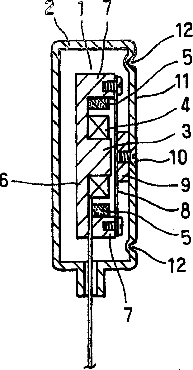
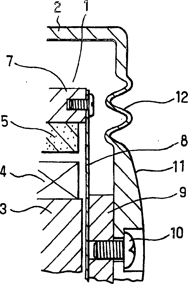
[0015] figure 1 It is a longitudinal sectional view showing an embodiment of the bone conduction speaker of the present invention. figure 2 It is an enlarged vertical cross-sectional view of main parts showing another embodiment. The bone conduction speaker of the present invention includes a bone conduction speaker assembly 1 and a casing 2 for accommodating the bone conduction speaker assembly 1 .

[0016] Generally, the bone conduction speaker assembly 1 has: a ring-shaped voice coil 4 that winds the center magnetic pole 3; Plate 8, a vibrating block 9 fixed on the upper surface of the vibrating plate 8. The vibrating mass 9 is fixed on the t...


PUM


Abstract

The objective of the invention is to provide a bone conduction device, in particularly employed in the receiver of a bone conduction telephone, which is capable of obtaining sufficient sound quantities as to not only bone conduction sound but also aerial vibration sound to ensure clear reception of sound. The bone conduction device comprises a bone conduction device unit and a case receiving the same to serve as a vibration section, and is characterized in that a compliance increasing mechanism, such as corrugations, is disposed along the peripheral edge of the vibrating surface of the case having the bone conduction device unit fixed thereto.

Description

technical field [0001] The present invention relates to a bone conduction device, and more specifically, to a bone conduction device that is a speaker or a microphone that transmits a sound signal as bone conduction sound, and is installed in a telephone or the like even if it is not pressed tightly. It does not impair the sense of volume even if it is used on the head. Background technique [0002] For example, a bone conduction speaker includes: a bone conduction speaker assembly 21, which has a ring-shaped voice coil 24 that winds a central magnetic pole 23, a magnet 25 disposed along the inner peripheral surface of a peripheral wall 27 at the periphery of a yoke 26, and a The vibrating plate 28 on the upper surface, the vibrating block 29 fixed on the upper surface of the vibrating plate 28; the housing 22 that accommodates the bone conduction speaker assembly 21; , thus the bone conduction speaker assembly 21 becomes a structure arranged in the housing 22 ( Figure 4 )...

Claims


Application Information

Patent Timeline
Patent Type & Authority Applications(China)
IPC IPC(8): H04R1/00H04R7/26H04R1/02H04R1/10
CPCH04R2460/13H04R1/1091H04R2499/11H04R9/066H04R25/606H04R1/00H04R1/02H04R7/26H04R13/00
Inventor 小林一二
Owner TEMCO JAPAN
Why Eureka
Try Eureka