Machine tool cutter automatic replacing device

A technology for automatic replacement of machine tools, applied in the field of machine tools, can solve the problems of long tool change time, high cost, inability to perform high-speed rotation positioning of heavy tools, and achieve the effect of improving working space and simple structure

Inactive Publication Date: 2010-07-28
WEIHAI HUADONG AUTOMATION
View PDF7 Cites 2 Cited by
  • Summary
  • Abstract
  • Description
  • Claims
  • Application Information

AI Technical Summary

Problems solved by technology

Since the tools are arranged on the entire circumference, the processing area is occupied, resulting in a narrow processing area (the size of the workpiece that can be processed), and the entire track of the cylinder and the "bamboo hat" is required, so the structure is complicated and the cost is high. In addition, there is no way to prevent the tool from flying out. The locking mechanism cannot perform high-speed rotary positioning of heavy tools, and the tool change time is long

Method used


Image

  • Machine tool cutter automatic replacing device
  • Machine tool cutter automatic replacing device
  • Machine tool cutter automatic replacing device

Examples


Embodiment Construction

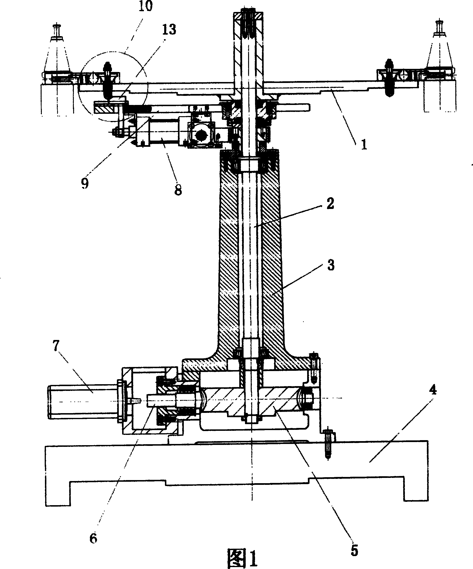
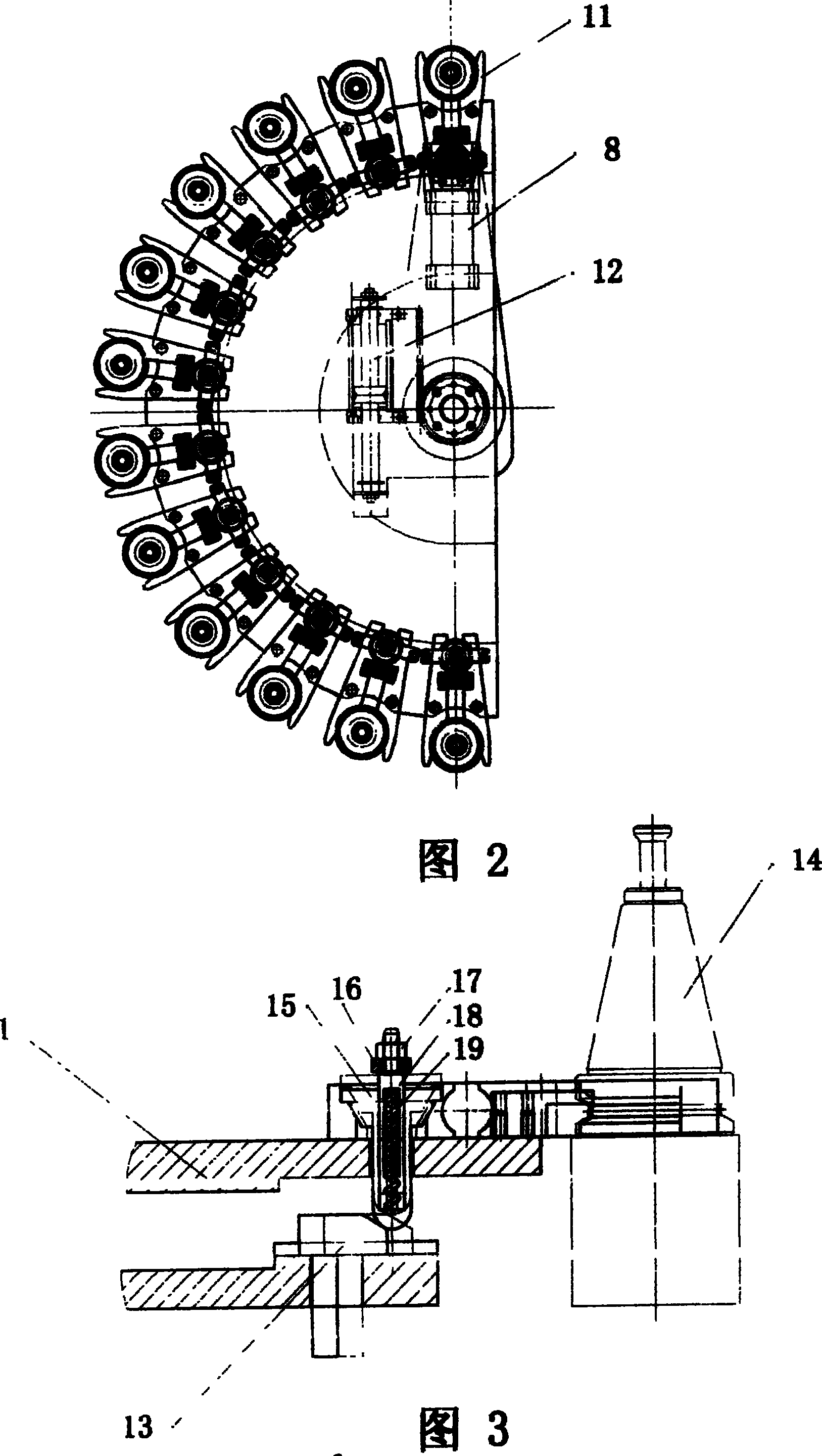
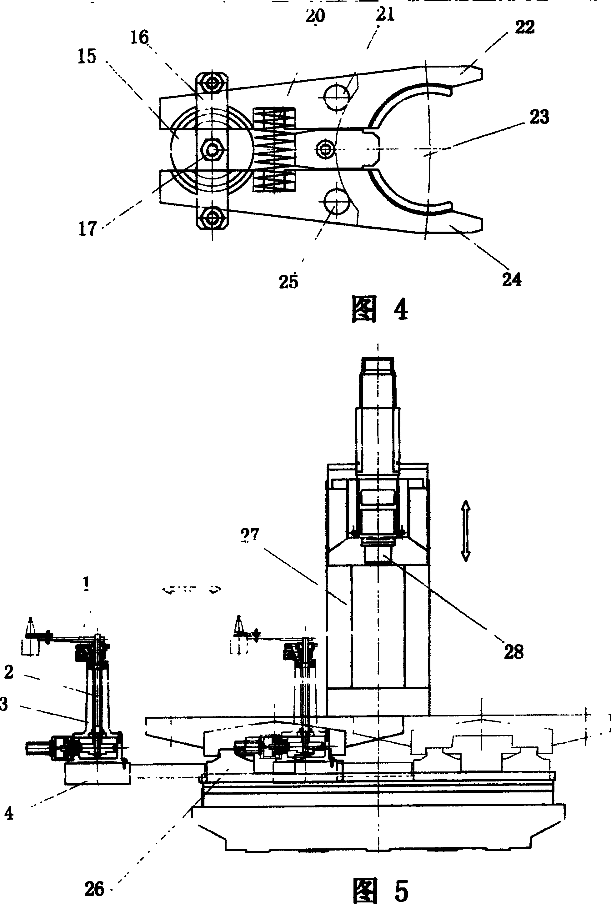
[0017] exist figure 1 , figure 2 , image 3 , Figure 4 , Figure 5 Among them, the tool magazine base 4 and the saddle 26 move synchronously along the X direction of the machine tool. The tool magazine support 3 is vertically fixed on the tool magazine base 4, and the inner cavity sleeve in the axial direction of the tool magazine support 3 is inserted with a rotating shaft 2. The lower end of 2 meshes with the worm 6 through the worm gear 5, the worm 6 is driven by the servo motor 7, the upper end of the rotating shaft 2 is fixed with the center of the cutter head 1, the cutter head 1 can rotate with the rotating shaft 2, and the included angle of the cutter head 1 is 180-degree fan-shaped disk, the cutter head 1 of the present invention can also be a fan-shaped disk with an included angle of 210 degrees, 240 degrees, and 270 degrees. Clamps 11 are evenly distributed. The clamp 11 is composed of a left jaw 22 and a right jaw 24. The left jaw 22 and the right jaw 24 ar...


PUM


Abstract

The invention relates to a machine tool with a cutter head which is a sector disc whose angle is less than 270 degrees. Several clamps are uniformly distributed along the circle of said sector disc; the cutter head is mounted at the upper end of rotation shaft, which is inserted in the bracket; the bracket is vertically mounted on the support which is interlocked with the cradle; the lower end ofrotation shaft is meshed with worm via worm wheel, while the worm is driven by servo-motor; left and right gripping jaws are individually mounted on the cutter head via left and right rotation shafts; obconic hole is arranged on the sheets at the left of left and right rotation shafts and the left of left and right gripping jaws; the axial center of obconic hole is at the connection part of left and right gripping jaws; a cylinder hole is arranged along the axial direction of sliding rod; a space is arranged between the lower side surface of clamping plate and the upper surface of obconic hole, while a inclined dovetail with one inclined end-surface is mounted at the lower end of sliding rod. The invention can realize the change of knives between cutter head and main axis.

Description

technical field [0001] The invention relates to the field of machine tools, in particular to an automatic changing device for machine tools. Background technique [0002] The existing automatic tool changer for machine tools generally adopts a "bamboo hat-type tool magazine", and the clamps for holding tools are evenly arranged on a 360-degree circle, and the tool is loaded and unloaded through the movement of the mechanical Z-axis. Driven by air cylinders, etc., there is no mechanism (locking mechanism) to prevent the tool from flying out. Since the tools are arranged around the entire circumference, the processing area is occupied, resulting in a narrow processing area (the size of the workpiece that can be processed), and the entire track of the cylinder and the "bamboo hat" is required, so the structure is complicated and the cost is high. In addition, there is no way to prevent the tool from flying out. The locking mechanism cannot perform high-speed rotary positioning...

Claims


Application Information

Patent Timeline
Patent Type & Authority Patents(China)
IPC IPC(8): B23Q3/155B23Q3/157
CPCB23Q3/15722B23Q3/15713B23Q2003/155418B23Q2003/155428B23Q2003/155442B23Q2003/155446
Inventor 大平研五安丰锐
Owner WEIHAI HUADONG AUTOMATION
Why Eureka
Try Eureka