Automatic set for changing tools in use for machine

An automatic tool replacement technology, applied in the field of machine tools, can solve the problems that must be installed on another device, the overall weight is increased, and the tool replacement speed is not very fast, and the effect of avoiding adverse effects and simple structure is achieved.

Inactive Publication Date: 2008-08-27
WEIHAI HUADONG AUTOMATION
View PDF10 Cites 0 Cited by
  • Summary
  • Abstract
  • Description
  • Claims
  • Application Information

AI Technical Summary

Problems solved by technology

[0002] CN 1455715A discloses a machine tool with a tool spindle and a tool changer. The conveying mechanism of the tool changer has a support part that can rotate around a rotation axis that is inclined to the main axis, and is hinged on the support part. The claw that rotates on the axis of the axis is provided with some guide mechanisms on the support member, and these guide mechanisms are rotatably supported around the first axis of rotation parallel to the axis of rotation and in the direction opposite to the direction of rotation of the support member around the axis of rotation These guide mechanisms are respectively rotatably connected to a claw around a second rotation axis extending parallel to the main axis. Although it can automatically realize the function of changing tools, the structure is complicated and the speed of changing tools is still not very fast. quick
For horizontal machine tools, it is necessary to be able to use many tools, and the overall weight of the cutter head that stores many tools will increase. Especially for small horizontal machine tools with movable spindles, the cutter head cannot be installed on the spindle X moving mechanism, so it can The cutter head that stores a large number of tools has to be arranged on a fixed part outside the moving mechanism, which increases the distance between the tool cutter head and the spindle. The cutter head of the medium tool that stores the necessary tools in the processing technology is installed on the moving part of the main shaft, and the tool change is adopted automatically. The tool exchange of the cutter head storing a large number of tools and the cutter head of the medium tool must be done in another On the device, it is performed when the machining is stopped, so two tool exchange devices are required, and the structure is also complicated

Method used


Image

  • Automatic set for changing tools in use for machine
  • Automatic set for changing tools in use for machine

Examples


Embodiment Construction

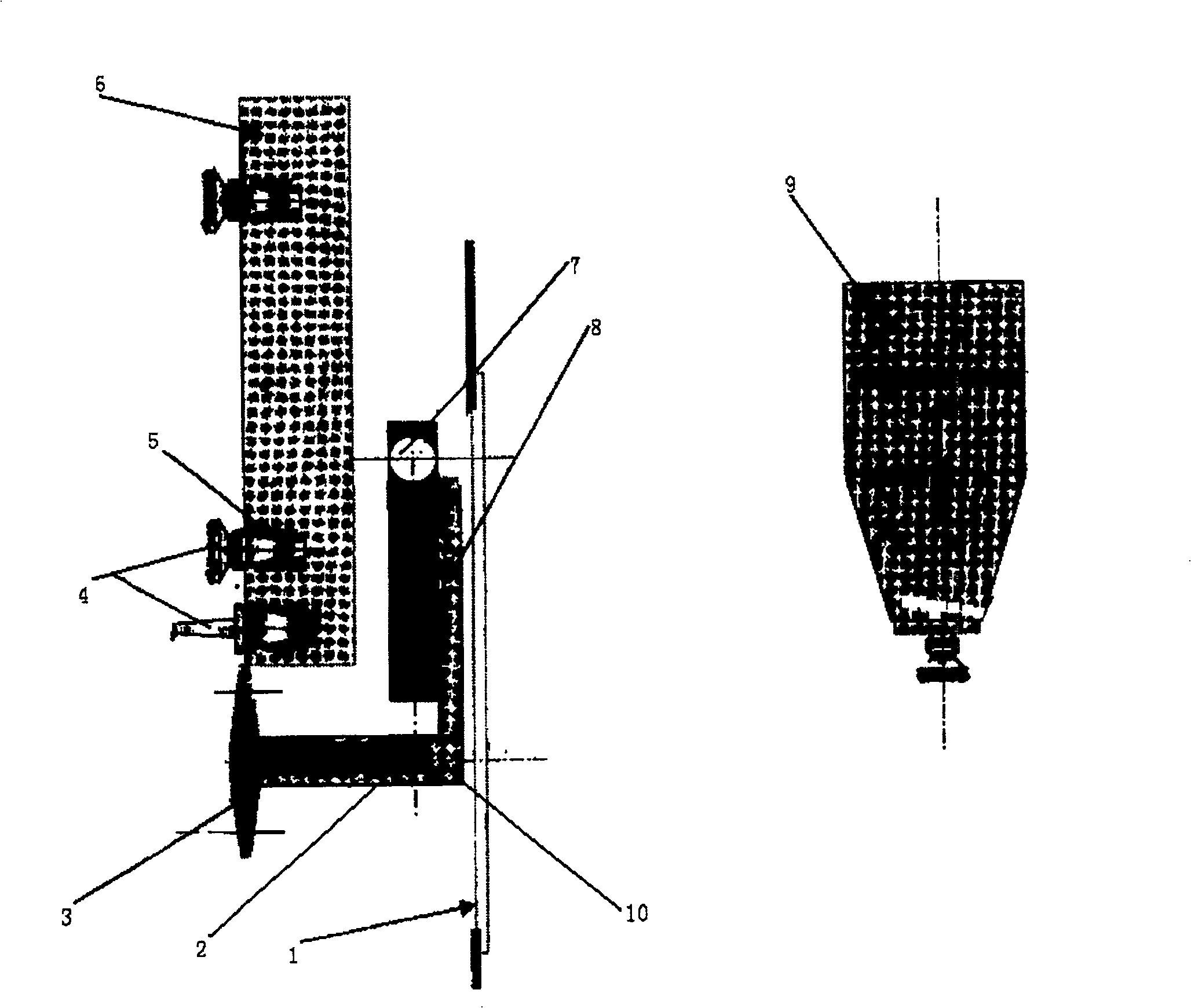
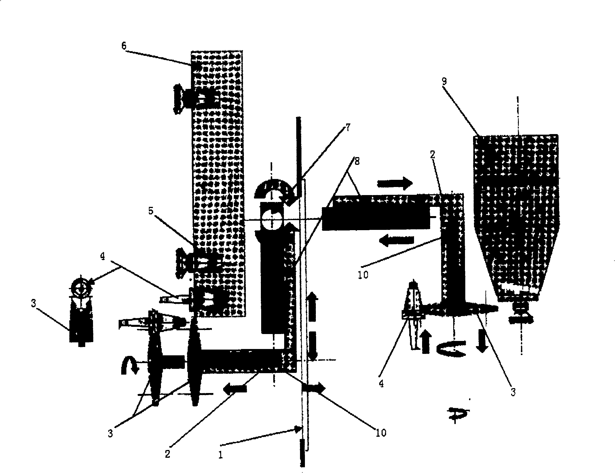
[0012] exist figure 1 Among them, the tool cutter head 6 can rotate around its own rotating shaft. The rotating shaft of the tool cutter head 6 is perpendicular to the machine tool spindle 9. The axis of the machine tool spindle 9 is parallel to the disk surface of the tool cutter head 6. The storage hole 5 of the storage tool 4, between the tool cutter head 6 and the machine tool spindle 9, a rotary shaft 7 is installed near the inner surface of the tool cutter head 6, the rotary shaft 7 is perpendicular to the rotating shaft of the tool cutter head 6 and the machine tool spindle 9, and Parallel to the disk surface of the tool cutter head 6, the rotary shaft 7 is hinged with the upper end of the telescopic rod 8, that is, the telescopic rod 8 can rotate around the rotary shaft 7, and the length of the telescopic rod 8 can be elongated or shortened as required, and the lower end of the telescopic rod 8 It is fixed together with the right end of the pole 2, the pole 2 is perpen...


PUM


Abstract

An automatic tool exchanger for machine-tool is composed of a tool disk with holes for storing tools in them, a rotary axle perpendicular to the tool disk and pivoted to top end of a telescopic rod, a telescopic rod whose lower end is fixed to one end of a supporting rod, and a tool exchanging arm whose middle position is pivoted to another end of supporting rod.

Description

Technical field [0001] The invention relates to the field of machine tools, in particular to a device capable of automatically replacing tools used on the main shaft of the machine tool. Background technique [0002] CN 1455715A discloses a machine tool with a tool spindle and a tool changer. The conveying mechanism of the tool changer has a support part that can rotate around a rotation axis that is inclined to the main axis, and is hinged on the support part. The claw that rotates on the axis of the axis is provided with some guide mechanisms on the support member, and these guide mechanisms are rotatably supported around the first axis of rotation parallel to the axis of rotation and in the direction opposite to the direction of rotation of the support member around the axis of rotation These guide mechanisms are respectively rotatably connected to a claw around a second rotation axis extending parallel to the main axis. Although it can automatically realize the function ...

Claims


Application Information

Patent Timeline
Patent Type & Authority Patents(China)
IPC IPC(8): B23Q3/157
Inventor 大平研五秦之旭
Owner WEIHAI HUADONG AUTOMATION
Why Eureka
Try Eureka