Electronic volume

A technology of electronic potentiometers and resistors, which is applied to electrical components, impedance networks, discontinuous tuning with variable adjustment elements, etc., can solve the problems of large-scale electronic potentiometers, increase the size of MOS transistors, etc., and achieve overall small size Minimize, achieve attenuation, and simplify the effect of the drive circuit

Active Publication Date: 2006-05-31
NEW JAPAN RADIO CORP
View PDF1 Cites 2 Cited by
  • Summary
  • Abstract
  • Description
  • Claims
  • Application Information

AI Technical Summary

Problems solved by technology

Therefore, in order to reduce the on-resistance of the switches S51 to S54, there is a need to increase the size of the MOS transistors constituting the switches, and there is a problem of increasing the size of the electronic potentiometer.

Method used


Image

  • Electronic volume
  • Electronic volume
  • Electronic volume

Examples


Embodiment Construction

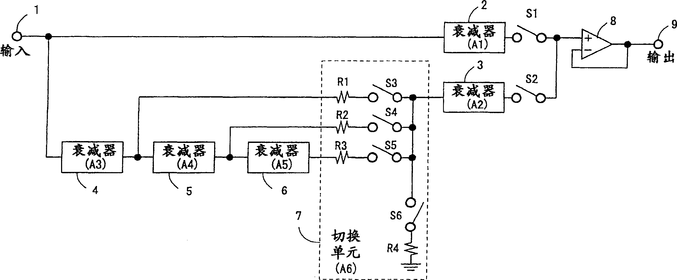
[0019] figure 1 It is a block diagram for explaining the principle of the electronic potentiometer of the present invention. Among them, 1 is the signal input terminal, 2 is the first attenuator (attenuation A1), 3 is the second attenuator (attenuation A2), 4 is the third attenuator (attenuation A3), 5 is the fourth attenuator ( Attenuation A4), 6 is the fifth attenuator (attenuation A5), 7 is the switcher (attenuation A6), 8 is the output buffer adopting the voltage follower structure, and 9 is the signal output terminal. S1 to S6 are switches, and in particular, the on-resistances of the switches S3 to S6 of the switcher 7 are the same value. In addition, the resistors R1 to R4 of the switcher 7 are resistors of the same value.

[0020] Among the electronic potentiometers, when only the switch S1 is turned on, the attenuation amount A1 of the attenuator 2 can be realized. Since the input impedance of the output buffer 8 is large at this time, there is no current in the s...


PUM


Abstract

Electronic potentiometer to reduce errors caused by switch on-resistance. The first attenuator 2 connected to the signal input terminal 1 by the input end, the first switch S1 connected between the output end of the first attenuator 2 and the input end of the output buffer 8, the second attenuator 3, the connection The second switch S2 between the output end of the second attenuator 3 and the input end of the output buffer 8, three attenuators 4, 5, 6 connected in series on the signal input terminal 1, connected to the three A switch 7 between each output terminal of the attenuator and the input terminal of the second attenuator 3 is constituted. Switcher 7 is connected on the output end of above-mentioned three attenuators by one end, and the other end is connected in the resistance of the input end of above-mentioned the 2nd attenuator 3 and three series circuits of switch (R1 and S3, R2 and S4, R3 and S5 ), and a series circuit (R4 and S6) of resistors and switches connected in series between the other end of the series circuit and ground.

Description

technical field [0001] The present invention relates to an electronic potentiometer capable of eliminating error components caused by on-resistance of switches and realizing high-precision attenuation. Background technique [0002] As the current electronic potentiometer, most of them have Figure 6 The circuit of the weighting method is shown. exist Figure 6 Among them, 1 is a signal input terminal, R51-R62 are resistors, S51-S62 are switches, 8 is an output buffer with a voltage follower structure, and 9 is a signal output terminal. [0003] In the electronic potentiometer, by selecting and turning on any one of the switches S51-S54, the attenuation of 0-3dB in steps of 1dB can be realized in the resistance group of the resistors R51-R54. In addition, by turning on any one of the switches S56-S62, the attenuation of -4--28dB in steps of 4dB can be realized in the resistance group of the resistors R55-R62. Therefore, by combining an on switch in the switch group S51-S54 ...

Claims


Application Information

Patent Timeline
Patent Type & Authority Applications(China)
IPC IPC(8): H03H7/24H03J5/08
CPCH03G1/0088H03H7/24
Inventor 杉本芳嗣
Owner NEW JAPAN RADIO CORP
Why Eureka
Try Eureka