Foot lever for wringing out a mop

A technology of pedals and mops, applied in the field of pedals

Inactive Publication Date: 2006-06-07
CARL FREUDENBERG KG
View PDF0 Cites 0 Cited by
  • Summary
  • Abstract
  • Description
  • Claims
  • Application Information

AI Technical Summary

Problems solved by technology

This wringing process is a bigger problem for the elderly or for pregnant women and those with certain problems, such as arthrosis or back pain, because they cannot apply the necessary force with their hands to achieve proper wringing of the mop

Method used


Image

  • Foot lever for wringing out a mop
  • Foot lever for wringing out a mop
  • Foot lever for wringing out a mop

Examples


Embodiment Construction

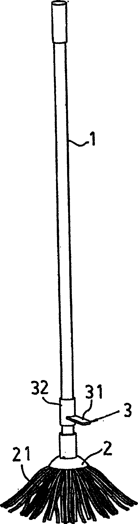
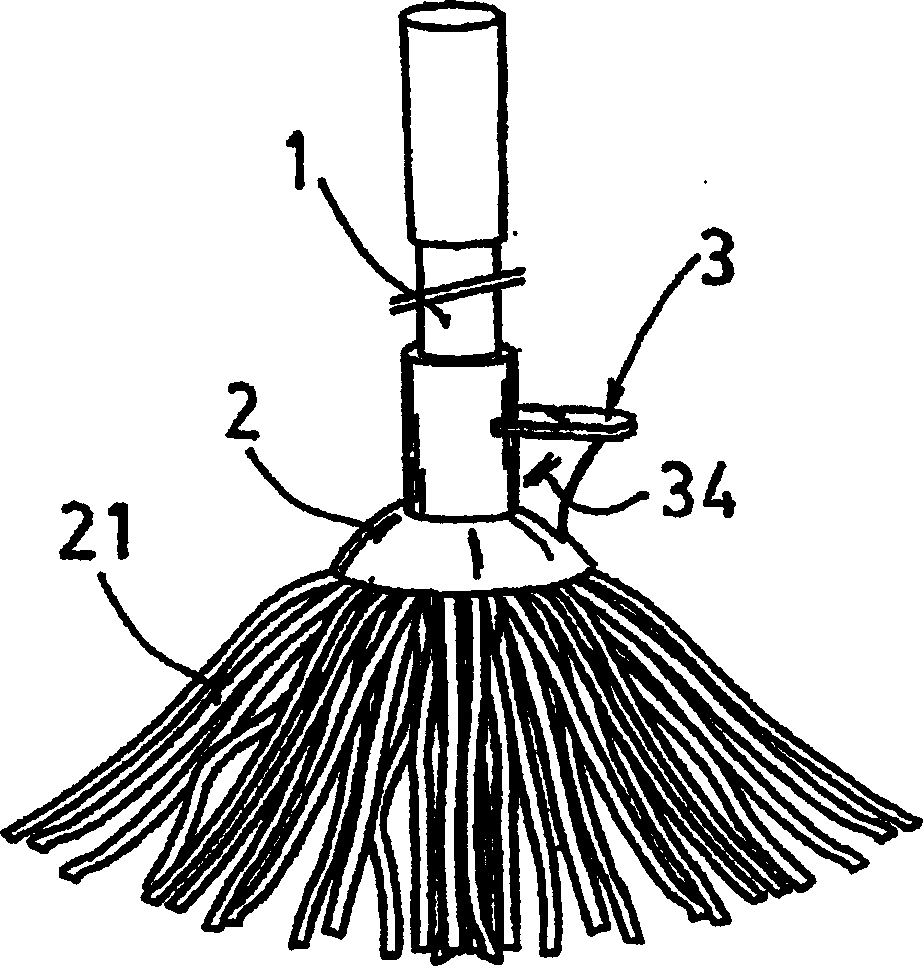
[0012] exist figure 1 Can see a common mop, it is designed as a bar 1 that is fixed on the head 2 that carries mopping bar 21;

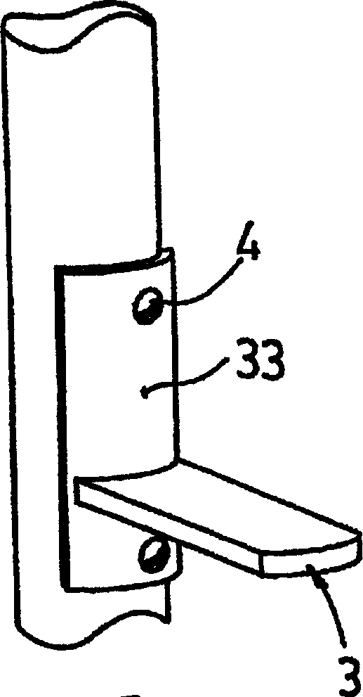
[0013] In this embodiment the pedal is formed by a lateral shoulder 3 which defines a top surface 31 for exerting pressure with the foot in the direction of the lower region when wringing the mop dry, which facilitates the wringing process.

[0014] shown in figure 1 The middle lateral shoulder 3 is provided with a tubular structure 32 perpendicular to said lateral shoulder 3 , which has a diameter large enough to allow the tubular structure to be mounted on the rod 1 freely in rotation and longitudinally. This possibility of movement of the pedal relative to the mop allows, in addition to comfort:

[0015] - Guarantee, that it remains by its own weight in the lower area of ​​the rod,

[0016] - The lateral shoulders are arranged radially for the most comfortable squeezing with the feet when the head is placed on the squeeze grid of the bucket,

...


PUM


Abstract

The pedal includes a convex shoulder (3) on one side, which is set in the area near the connection part of the mop head (2) and pole (1), and it has one top for one to press the feet during the squeezing trailer.Noodles (31).The side convex shoulder (3) can be limited on the pole (1) or head (2), and has an element that is used to motion or rigidly install it on the pole (1) or head (2), 33), and it is basically perpendicular to the direction of the pole (1) geometric axis.

Description

technical field [0001] The present invention relates to a pedal which facilitates the process of wringing out a mop, of the type used for wiping surfaces and comprising a head carrying a number of ears or strips of rags and a rod attached to a on the head for easy grip and operation of the mop. Background technique [0002] Such mops are well known today, which are used to mop floors and are used together with a bucket carrying a grid for squeezing, so that the ears or strips of the mop can saturate the liquid contained in the bucket and then be squeezed by squeezing the grid. Press to remove excess water. [0003] With commercially available mops, the wringing process requires a relatively high force on the rod, wherein this process can only be performed by hand. This wringing process is a greater problem for the elderly or for pregnant women and those with certain problems, such as arthrosis or back pain, because they cannot apply the necessary force with their hands to ...

Claims


Application Information

Patent Timeline
Patent Type & Authority Applications(China)
IPC IPC(8): A47L13/00A47L13/14A47L13/20A47L13/24A47L13/58
CPCA47L13/58A47L13/14
Inventor M·D·L·M·马克斯本胡梅亚
Owner CARL FREUDENBERG KG
Why Eureka
Try Eureka