Eureka AIR delivers breakthrough ideas for toughest innovation challenges, trusted by R&D personnel around the world.

Emergency stop system of elevator

An emergency, elevator technology, applied in elevators, transportation and packaging, etc., can solve the problems of increased guide rail wear and damage, shortened guide rail life, and hindering the long life of the safety braking system.

Inactive Publication Date: 2006-06-07
MITSUBISHI ELECTRIC CORP
View PDF1 Cites 46 Cited by
  • Summary
  • Abstract
  • Description
  • Claims
  • Application Information

AI Technical Summary

Problems solved by technology

[0003] In such an elevator device, in order to improve the operational reliability of the ropeless governor, it is necessary to perform frequent operational tests. However, since the ropeless governor comes into intense contact with the guide rails every time an operational test is performed, the wear and tear of the guide rails will be reduced. and damage increase, the life of the guide rail is shortened
In this way, the contact between the ropeless speed governor and the guide rail hinders the long life of the safety brake system

Method used


Image

  • Emergency stop system of elevator
  • Emergency stop system of elevator
  • Emergency stop system of elevator

Examples


Embodiment approach 1

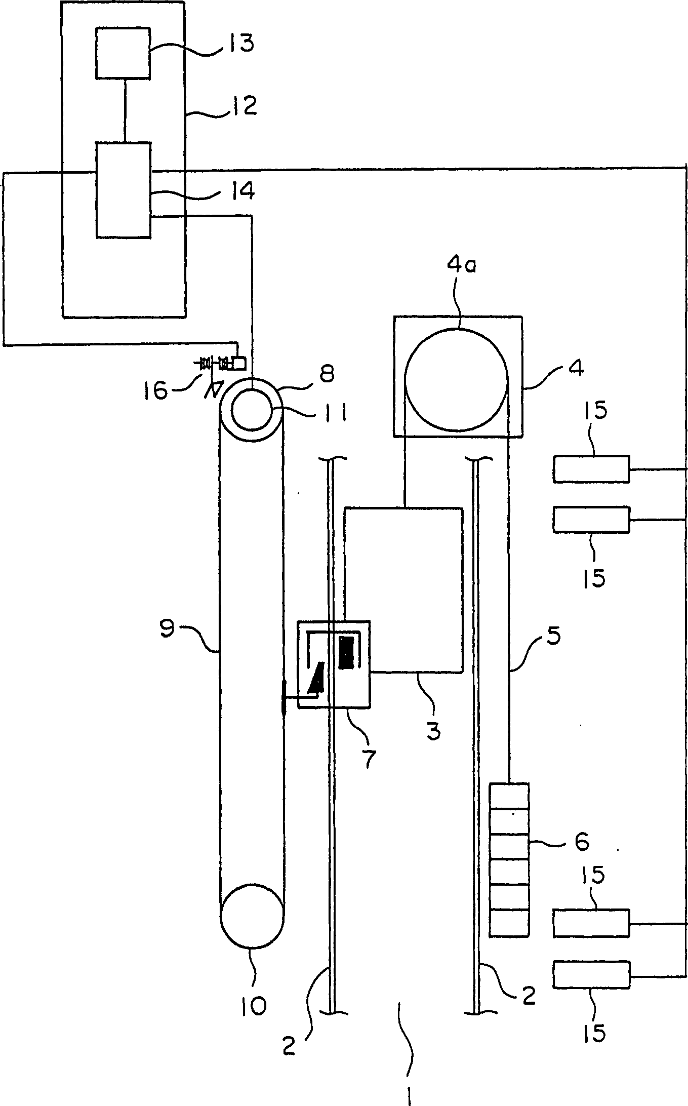
[0022] figure 1 It is a configuration diagram schematically showing the elevator apparatus according to Embodiment 1 of the present invention. In the drawing, a pair of car guide rails 2 is provided in a hoistway 1 . The car 3 is guided by the car guide rail 2 to move up and down in the hoistway 1 . At the upper end of the hoistway 1, a traction machine 4 serving as a driving device for raising and lowering the car 3 and the counterweight 6 is disposed. The main rope 5 is wound around the drive sheave 4a of the hoisting machine 4 . The car 3 and the counterweight 6 are suspended in the hoistway 1 by the main rope 5 . The hoisting machine 4 is provided with a brake device (not shown) that brakes the rotation of the drive sheave 4a.

[0023] On the car 3, a pair of emergency stop devices (braking parts) 7 interlocked with each other are attached so as to face the respective car guide rails 2 . Each emergency stop device 7 is arranged at the lower part of the car 3 . The ca...

Embodiment approach 2

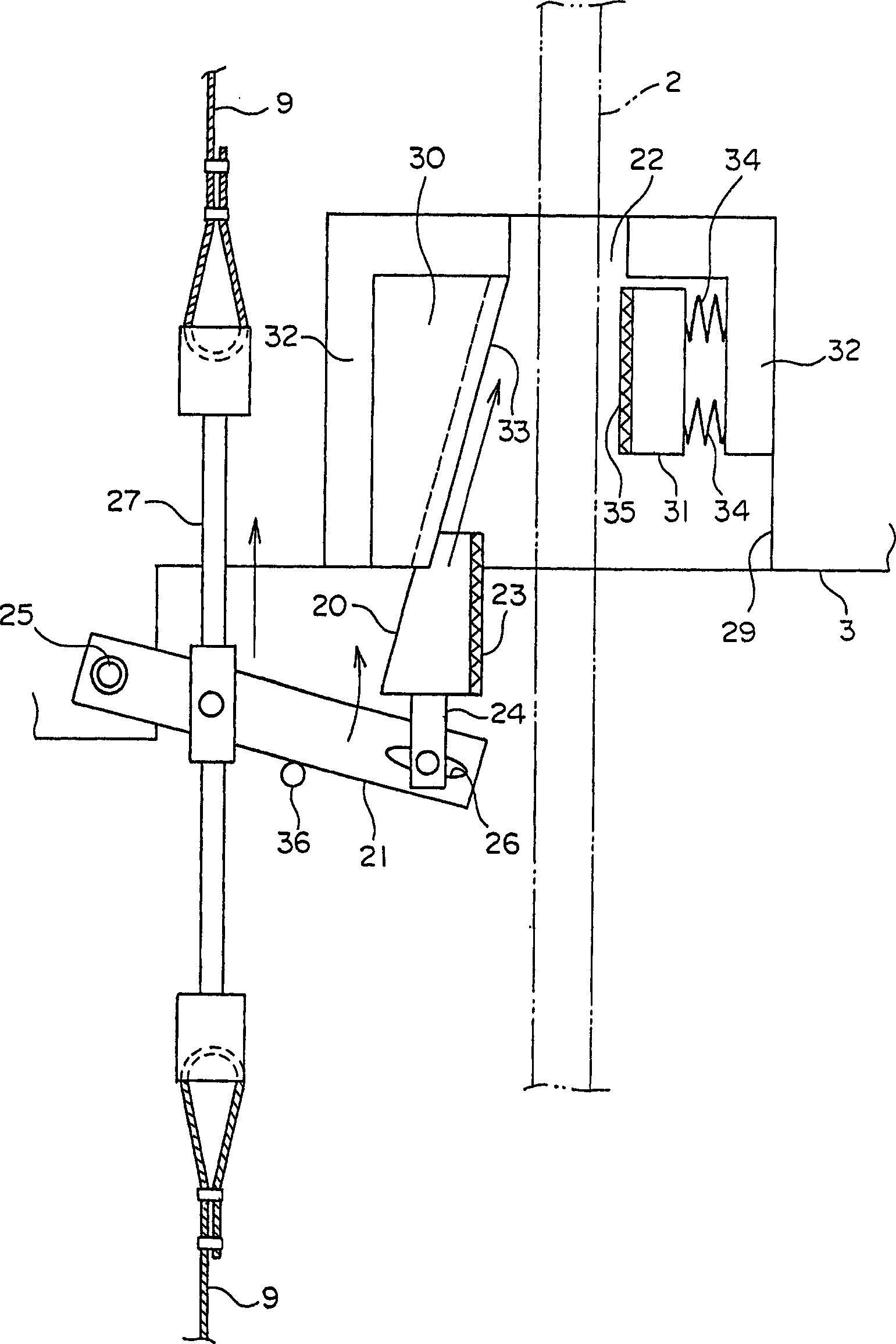
[0073] Figure 7 is a front view schematically showing an emergency stop device of an elevator emergency stop system according to Embodiment 2 of the present invention, Figure 8 yes means Figure 7 Side view of the emergency stop device in . In Embodiment 1, in order to brake the car 3, the car guide rail 2 is clamped by the wedge 20 and the pressing member 31, but as shown in the figure, the car guide rail 2 may be clamped by a pair of wedges 20. 2.

[0074] In the figure, each emergency stop device 7 comprises: a pair of wedges 20; Link mechanism 71, when it passes car 3 descends to the restraint of overspeed governor rope 9, makes each wedge 20 move relative to car 3; As The jaw member 72 of the guide portion guides each wedge 20 moved by the link mechanism 71 in a direction in which it comes into contact with the car guide rail 2 .

[0075] The link mechanism 71 includes: a connecting plate 73, one end of which is connected with the upper tie rod 27 in a rotatable man...

Embodiment approach 3

[0085] Figure 10 It is a configuration diagram showing a rope clamping device of an elevator emergency stop system according to Embodiment 3 of the present invention. In the figure, an electromagnetic actuator 81 is mounted on the mounting member 45 . The electromagnetic actuator 81 includes: a movable part 82, which can move between the working position where the brake shoe 42 is pressed to constrain the speed governor rope 9 and the release position where the restriction to the speed governor rope 9 is released; The pressing spring 83 applies force to the movable part 82 to the working position; the electromagnet 84 resists the biasing force of the pressing spring 83 to move the movable part 82 to the release position. The electromagnet 84 is mounted on the horizontal portion 46 .

[0086] The movable part 82 includes: a movable plate 85 attracted by the electromagnet 84 by energizing the electromagnet 84; and a movable rod 86 fixed on the movable plate 85 and penetrating...


PUM


Abstract

An emergency stop system of an elevator, wherein a governor rope moving in synchronism with the lifting of a car is wrapped around a governor sheave. An emergency stop device connected to the governor rope and braking the car by the displacement of the car relative to the governor rope is mounted on the car. A control device outputs operation signals when detecting the abnormality of the speed of the car. A rope catch device is installed near the governor sheave. The rope catch device comprises an electromagnetic actuator operated by the operation signals inputted therein and a restraining part restraining the governor rope by the operation of the electromagnetic actuator.

Description

technical field [0001] The present invention relates to an emergency stop system of an elevator for forcibly stopping a car traveling at an abnormal speed. Background technique [0002] In the conventional elevator apparatus, in order to prevent the car from falling, for example, as shown in Japanese Patent Application Laid-Open No. 2002-532366, a ropeless speed governor operated by an electromagnet is used. The ropeless speed limiter is engaged with the safety braking system. The ropeless speed governor makes contact with the guide rail through the action of an electromagnet. The safety braking system works using the resistance created by the contact of the ropeless overspeed governor with the guide rail. This brakes the car. [0003] In such an elevator device, in order to improve the operational reliability of the ropeless governor, it is necessary to perform frequent operational tests. However, since the ropeless governor comes into intense contact with the guide rail...

Claims


Application Information

Patent Timeline
Patent Type & Authority Applications(China)
IPC IPC(8): B66B5/06B66B5/04
CPCB66B5/044B66B5/06
Inventor 木川弘东中恒裕冈田峰夫
Owner MITSUBISHI ELECTRIC CORP
Why Eureka
Eureka Blog
Learn More