Supercharge Your Innovation With Domain-Expert AI Agents!

Side-blowing fan

A side-blown fan and fan blade technology is applied to non-variable-capacity pumps, components of pumping devices for elastic fluids, pump devices, etc., and can solve problems such as pressure relief and inability to further increase wind pressure.

Inactive Publication Date: 2006-08-16
DELTA ELECTRONICS INC
View PDF0 Cites 1 Cited by
  • Summary
  • Abstract
  • Description
  • Claims
  • Application Information

AI Technical Summary

Problems solved by technology

However, in this case, since the circular axial air inlet is almost not shielded by the upper and lower casings, when the rotation speed of the fan blade member 16 gradually increases, the airflow flowing therein can easily pass through the air inlet. Overflow to the outside world, resulting in pressure relief (or air leakage), which cannot further increase the wind pressure

Method used


Image

  • Side-blowing fan
  • Side-blowing fan
  • Side-blowing fan

Examples


Embodiment Construction

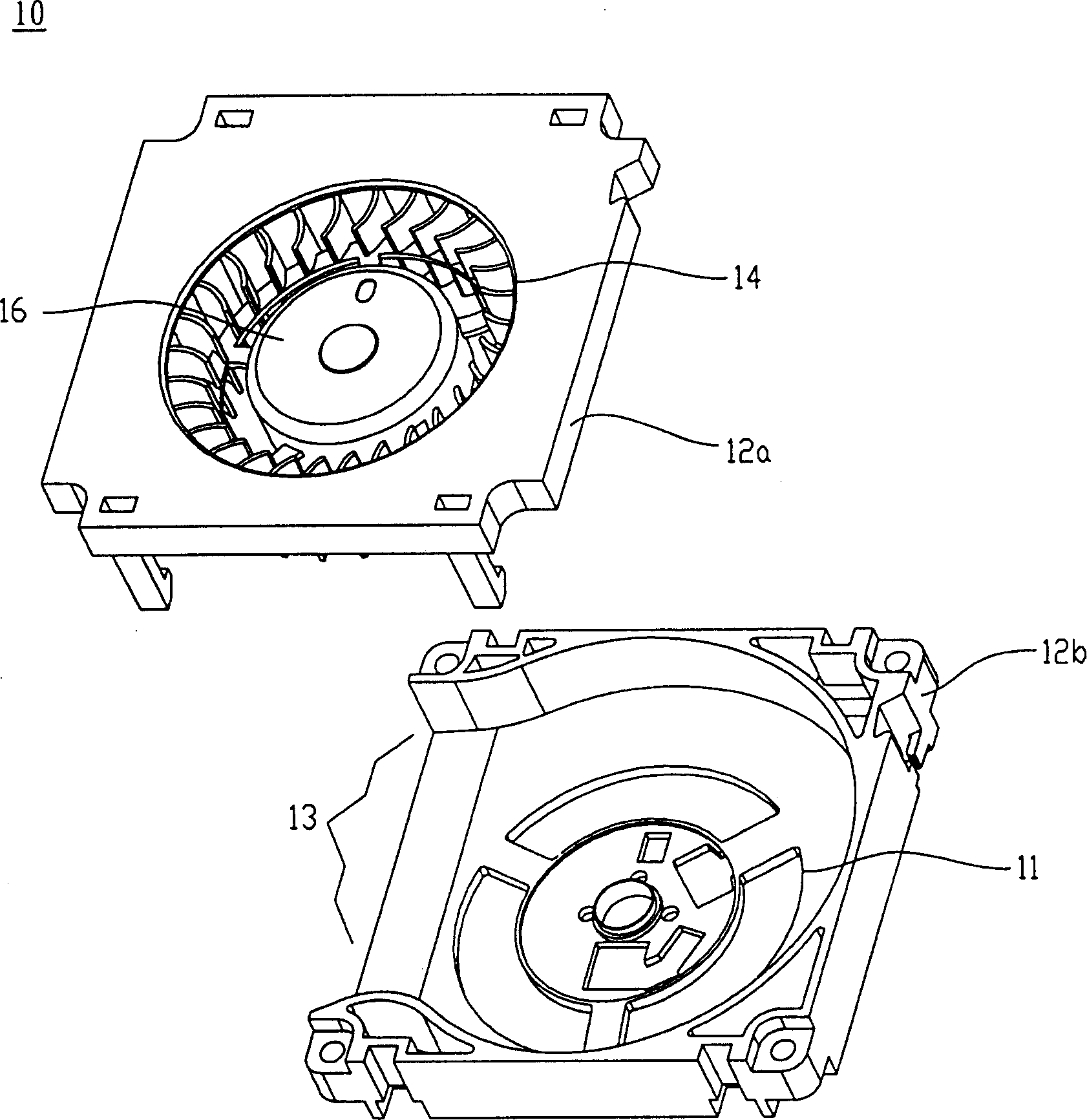
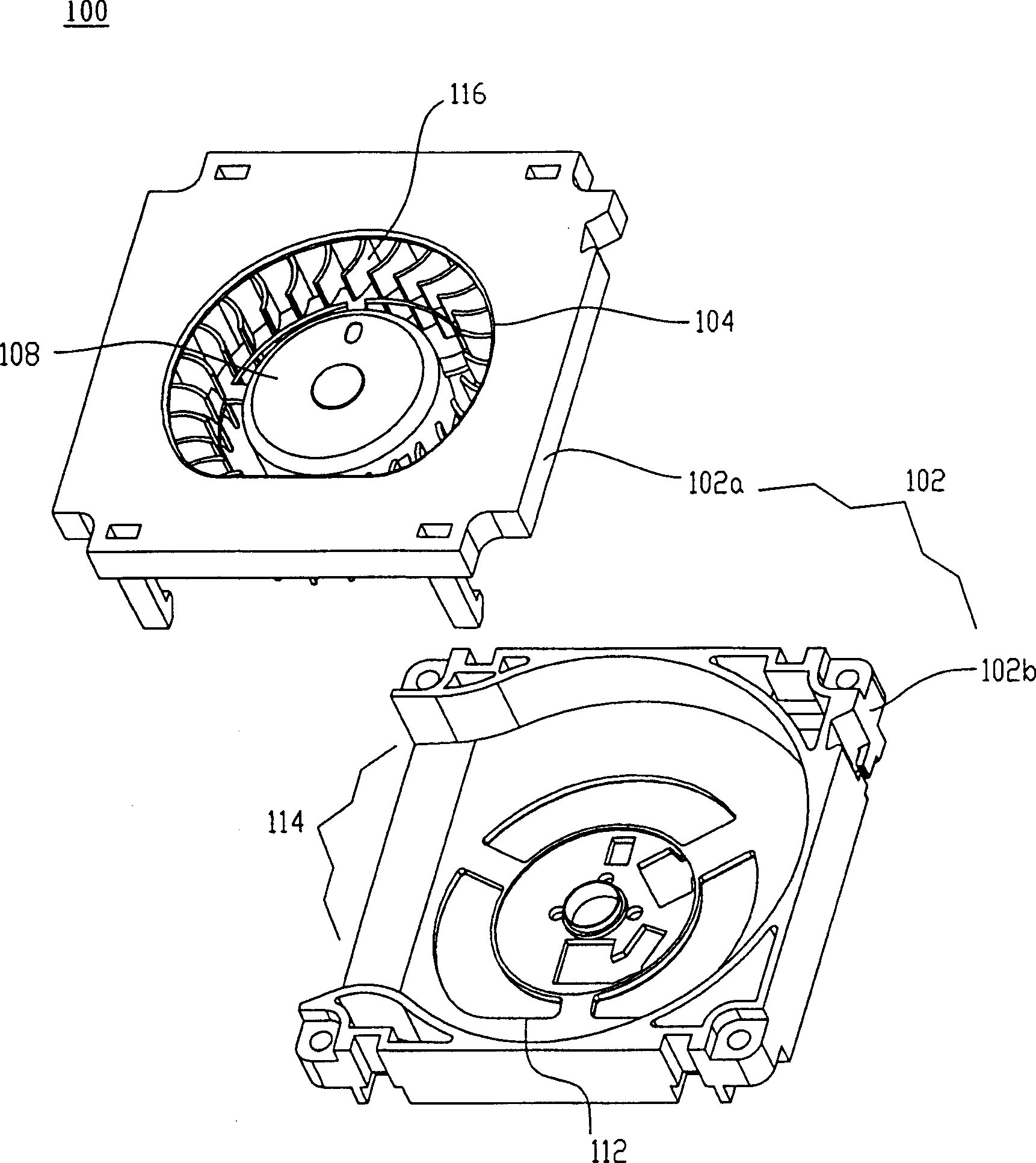
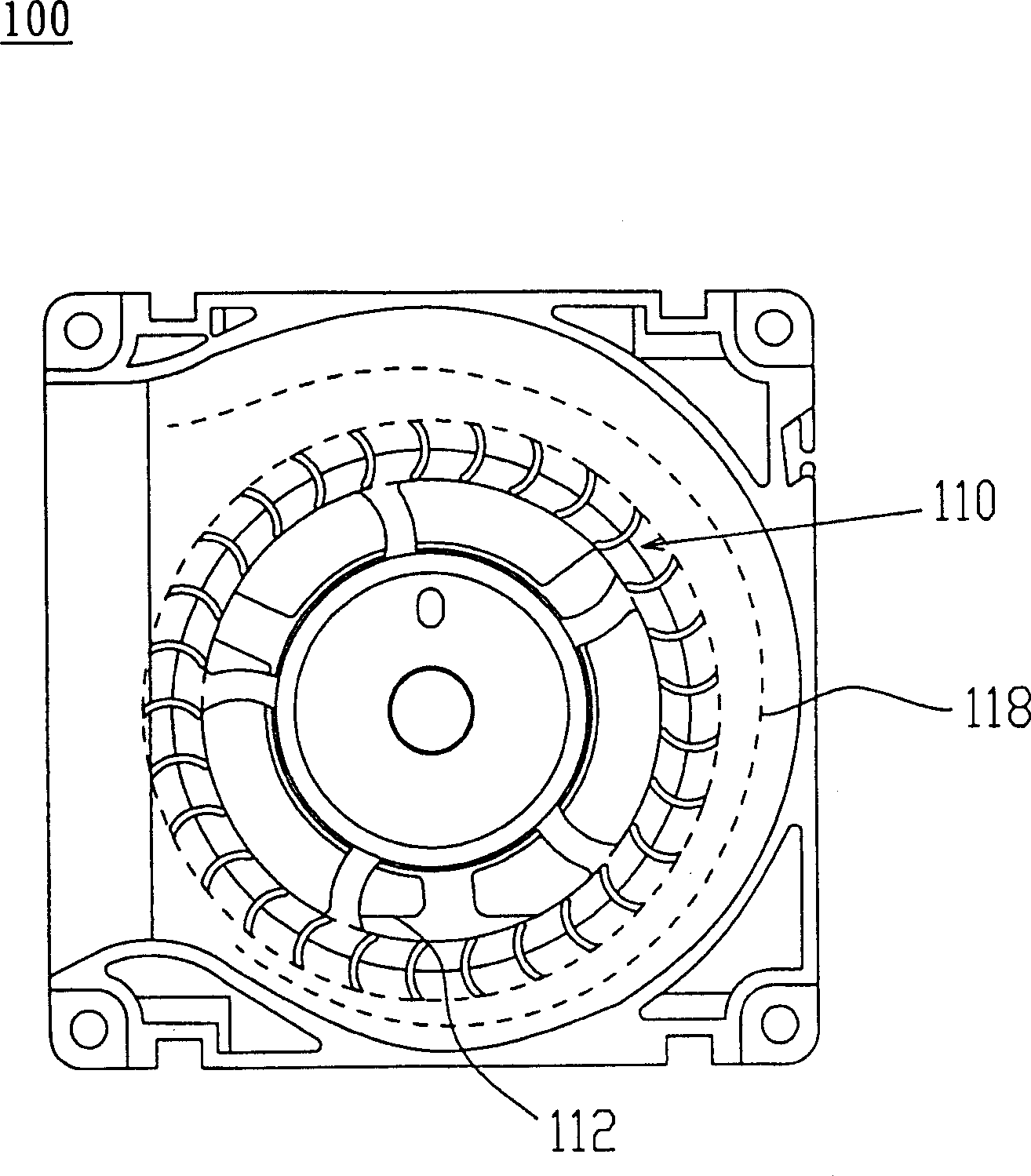
[0013] The present invention takes the form of a blower as an example to illustrate the side blowing fan of the present invention. Figure 2A Is a schematic diagram showing the side blowing fan 100 of the present invention, Figure 2B The figure is a perspective view of the present invention. Figure 4A , 4B Another embodiment of the present invention is shown.

[0014] as Figure 2A , Figure 2B As shown, the side-blowing fan 100 is composed of a casing 102 and a fan blade member 108, and there is an air duct 118 between the fan blade member 108 and the casing 102.

[0015] The housing 102 has lateral air outlets 114 and axial air inlets 104 and 112. The shape of the axial air inlets 104 and 112 is cut round air inlets, such as Figure 3A The elliptical air inlet 106a shown, such as Figure 3B The polygonal air inlet 106b shown, such as Figure 3C The circular air inlet 106c which is not coaxial with the axis of the fan blade member 108 or the air inlet of any closed shape is sho...


PUM


Abstract

A side-blown fan consists of a casing and a blade member inserted in the casing. The casing has a side air outlet and an axial air inlet in the shape of polygon, ellipsoid and the like. There is an air duct between the blade member and the casing.

Description

Technical field [0001] The present invention relates to a side blowing fan, in particular to a side blowing fan that reduces air leakage and increases wind pressure. Background technique [0002] In a system that requires a high back pressure, the prior art uses a blower to provide a higher wind pressure to the system, so that the system can obtain a higher back pressure. figure 1 The system shown is a schematic diagram of the structure of a prior art blower. Please refer to figure 1 The blower 10 is composed of an upper housing 12a, a fan blade member 16, and a lower housing 12b. The upper housing 12a has an axial air inlet 14, and the lower housing 12b has an axial air inlet 11, and is combined with the upper housing A lateral air outlet 13 is formed behind the lower casing 12b and 12a. [0003] In the above-mentioned prior art blower structure, the shape of the axial air inlets 14 and 11 is designed to be circular, and the axial air inlets 14 and 11 are coaxial with the fan ...

Claims


Application Information

Patent Timeline
IPC IPC(8): F04D25/08F04D29/44F04D29/42F04D29/02
Inventor 高毓键林祖亮蔡明熹黄文喜
Owner DELTA ELECTRONICS INC
Features
  • R&D
  • Intellectual Property
  • Life Sciences
  • Materials
  • Tech Scout
  • Unparalleled Data Quality
  • Higher Quality Content
  • 60% Fewer Hallucinations
Learn More