Driving circuit for nuclear power station reactor control stick

A technology for nuclear power plant reactors and drive circuits, applied in the power supply field, can solve problems such as large current ripple, poor follow-up characteristics, and complex circuits.

Inactive Publication Date: 2006-08-23
SHANGHAI PUHE TECH
View PDF0 Cites 19 Cited by
  • Summary
  • Abstract
  • Description
  • Claims
  • Application Information

AI Technical Summary

Problems solved by technology

At present, the drive of the control rod coil current still adopts the thyristor three-phase zero-type controllable rectification voltage regulation method, which has the disadvantages of complex circuit, large current ripple, and poor following characteristics.

Method used


Image

  • Driving circuit for nuclear power station reactor control stick
  • Driving circuit for nuclear power station reactor control stick
  • Driving circuit for nuclear power station reactor control stick

Examples


Embodiment Construction

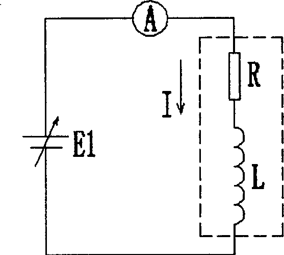
[0017] Coil current control method:

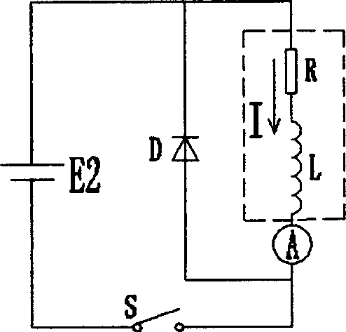
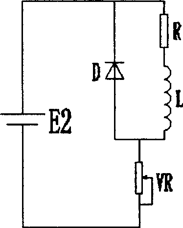
[0018] The circuit symbol of the rod control coil is represented by the series connection of resistance R and inductance L. Figure 1-a It is a coil voltage control method and a direct application of Ohm's law. Changing the output voltage of the controllable voltage source E1 changes the current in the coil RL. Figure 1-b E2 in E2 is a fixed voltage source, through the high-speed on-off control of the electronic switch S, the current in the coil RL can also be controlled. Figure 1-c The current in the coil can also be changed by changing the resistance value of the variable resistor VR connected in series.

[0019] Figure 1-c The additional loss of the method is too large and difficult to control, which is obviously not advisable. Figure 1-a The circuit looks simple, but in fact it is more Figure 1-b Much more complicated. Because it is very complicated to construct a controllable voltage source E1. Figure 1-b The fixed voltage ...


PUM


Abstract

This invention relates to a control rod drive circuit of a nuclear power plant reactor characterizing that said drive circuit applies a double topological structure of an adjustable circuit loop parameter, the electronic switches S1, S2 of the upper and lower arms of the circuit are serial to a connection resistor R< x > and a RC-absorption protection circuit RCD, S1 and S2 are connected to the middle point and R< x >, the RCD is connected with a quick successive current diode D after connecting to the middle point then to a DC power Ud and the D is parallel to the R and L of the coil, in which, the coil supply device of the rod-control system has very good drive and following ability for the rising and falling of current, very small stress of electronic switch and additive loss to control circuit.

Description

1. Technical field: [0001] The invention relates to a power supply technology, in particular to a nuclear power plant reactor control rod drive circuit 2. Background technology: [0002] Most of the nuclear power plants that have been built and are currently under construction use pressurized water reactors, and the control of their reactivity is mainly achieved by adjusting the position of the control rods in the core. The control rod driving power supply device is the key part of the rod control system, and its technical point is to drive high-quality and reliable currents of the three large-capacity electromagnet coils of the lifting coil, the fixed hook and the movable hook. At present, the current drive of the control rod coil still adopts the thyristor three-phase zero-type controllable rectification voltage regulation method, which has the disadvantages of complex circuit, large current ripple, and poor following characteristics. 3. Contents of the invention: [00...

Claims


Application Information

Patent Timeline
Patent Type & Authority Applications(China)
IPC IPC(8): G21C7/12
CPCY02E30/39Y02E30/30
Inventor 陈忠义
Owner SHANGHAI PUHE TECH
Why Eureka
Try Eureka