Supercharge Your Innovation With Domain-Expert AI Agents!

Plasma display device

A technology for plasma and display devices, applied in identification devices, selection devices, telemetry/remote selection devices, etc., can solve the problems of noise and vibration amplification, and the ineffectiveness of heat sinks to dissipate PDP heat.

Inactive Publication Date: 2006-08-30
SAMSUNG SDI CO LTD
View PDF0 Cites 0 Cited by
  • Summary
  • Abstract
  • Description
  • Claims
  • Application Information

AI Technical Summary

Problems solved by technology

Noise and vibration from the PDP may be further amplified on the driver board
Also, the heat sink may not be efficient enough to dissipate the heat from the PDP

Method used


Image

  • Plasma display device
  • Plasma display device
  • Plasma display device

Examples


Embodiment Construction

[0031] A plasma display device according to an embodiment of the present invention will be described in detail below with reference to the foregoing drawings. In the drawings, like reference numbers indicate identical or functionally similar elements.

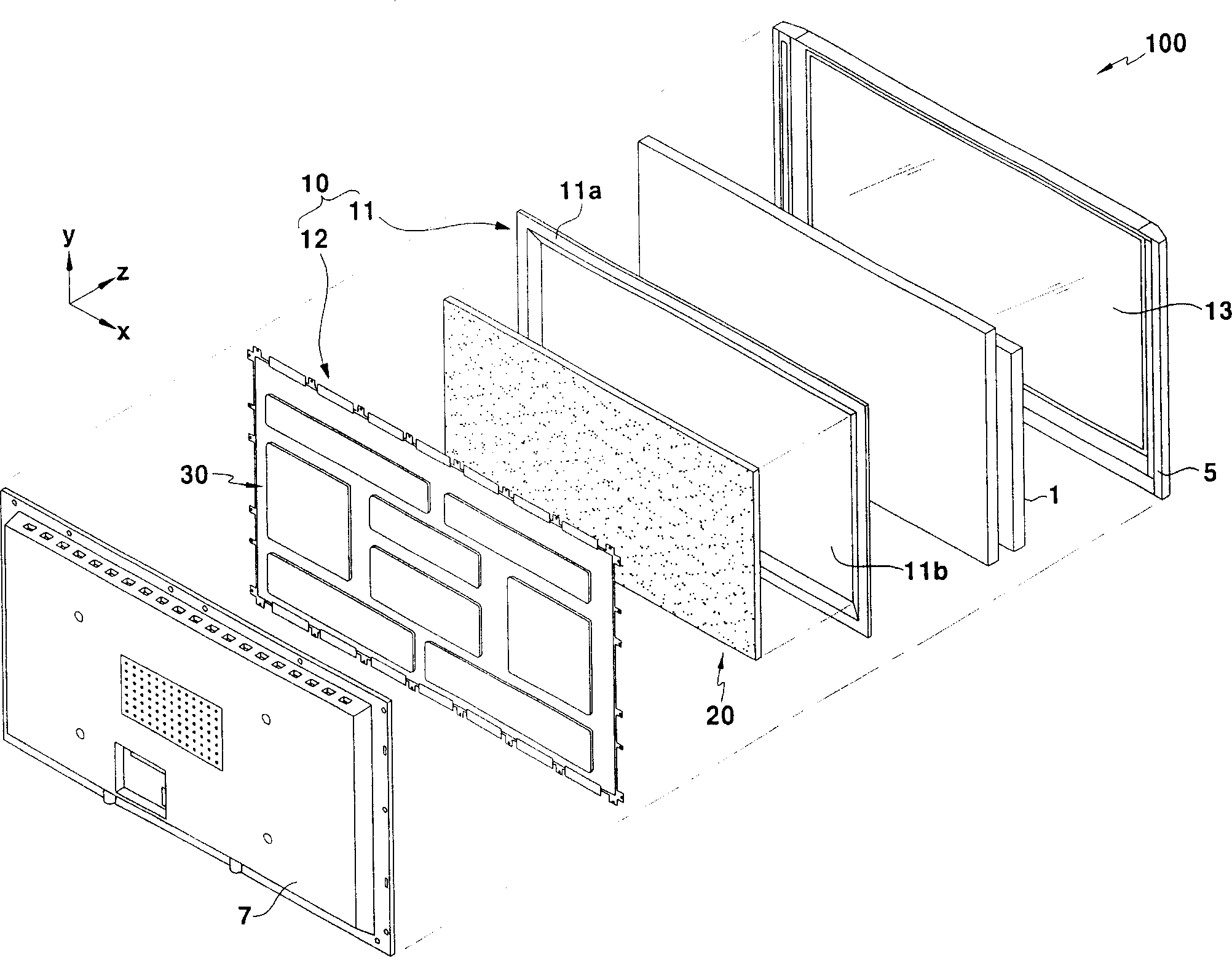
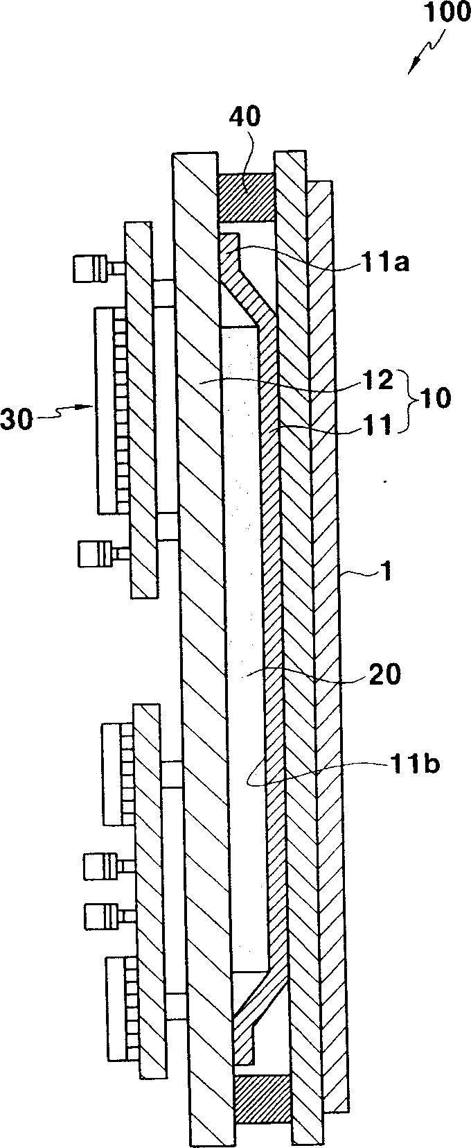
[0032] refer to figure 1 and figure 2 , to describe a plasma display device according to an embodiment of the present invention. exist figure 1 In this example, a plasma display device 100 includes a front cover 5, a PDP 1, a base substrate 10, a driving circuit 30, and a rear cover 7, all of which are placed parallel to each other. The PDP 1 is designed to display images on a front surface (not shown) facing the front cover 5 . The base substrate 10 is positioned on the opposite side of the PDP 1 from the front cover 5 . In the assembled structure, the surface of the base substrate 10 contacts the non-image display surface or rear surface of the PDP 1 . The driving circuit 30 is mounted on the other surface of the base ...


PUM


Abstract

A plasma display device which has improved performance of heat dissipation and noise / vibration insulation is disclosed. In one embodiment, the plasma display device includes a plasma display panel, a first base member coupled with the plasma display panel, a second base member connected to the first base member, and a thermally conductive cushion member interposed between the first base member and the second base member.

Description

technical field [0001] The invention relates to a plasma display device. More particularly, the present invention relates to a plasma display device having improved heat dissipation and noise / vibration isolation performance. Background technique [0002] In general, a plasma display panel (PDP) displays images by exciting fluorescent substances with ultraviolet (UV) rays. Ultraviolet light is generated by gas discharge in a vacuum discharge chamber. PDPs provide a wide screen in a light and thin design. In addition, PDPs have high performance in display capacity, brightness, contrast, and viewing angle. [0003] A plasma display device typically includes: a plasma display panel for displaying images; a base substrate supporting a PDP; a plurality of driving boards and a case. The driving board is mounted on the surface of the base substrate opposite to the surface supporting the PDP. The case is designed to encapsulate the PDP, the base substrate and the driver board. ...

Claims


Application Information

Patent Timeline
IPC IPC(8): G09F9/313H05K7/00H05K7/20G09F9/00
CPCH05K5/02H05K7/20963G08C17/02H04Q9/00H04M11/007G08C2201/50H04Q2209/43H04Q2209/30
Inventor 郑遇万
Owner SAMSUNG SDI CO LTD
Features
  • R&D
  • Intellectual Property
  • Life Sciences
  • Materials
  • Tech Scout
  • Unparalleled Data Quality
  • Higher Quality Content
  • 60% Fewer Hallucinations
Learn More