
Audio mixing console

A technology for mixers and mixers, applied in the field of mixers, which can solve problems such as dirty display surfaces, difficulty in accurately adjusting parameter values, and incorrectly changing parameter values

Inactive Publication Date: 2006-09-20
YAMAHA CORP
View PDF0 Cites 16 Cited by
  • Summary
  • Abstract
  • Description
  • Claims
  • Application Information

AI Technical Summary

Benefits of technology

It describes an improved way to select groups within a computer program called a spreadsheet. By referring to specific positions along one line (called rows) at different points), users are able to quickly identify what they want to work with next. They also have access to various options like adjustable thresholds or customizable buttons. Overall, this technology improves efficiency when working with data stored across many computers.

Problems solved by technology

Technological Problem addressed in this patents describes how operators face difficulties controlling many different aspects during mixed audio playback systems due to their limited physical movements required while selecting desired sounds through menu choices presented on panels at remote locations where they have access to external equipment like computers.

Method used


Image

  • Audio mixing console
  • Audio mixing console
  • Audio mixing console

Examples


Embodiment Construction

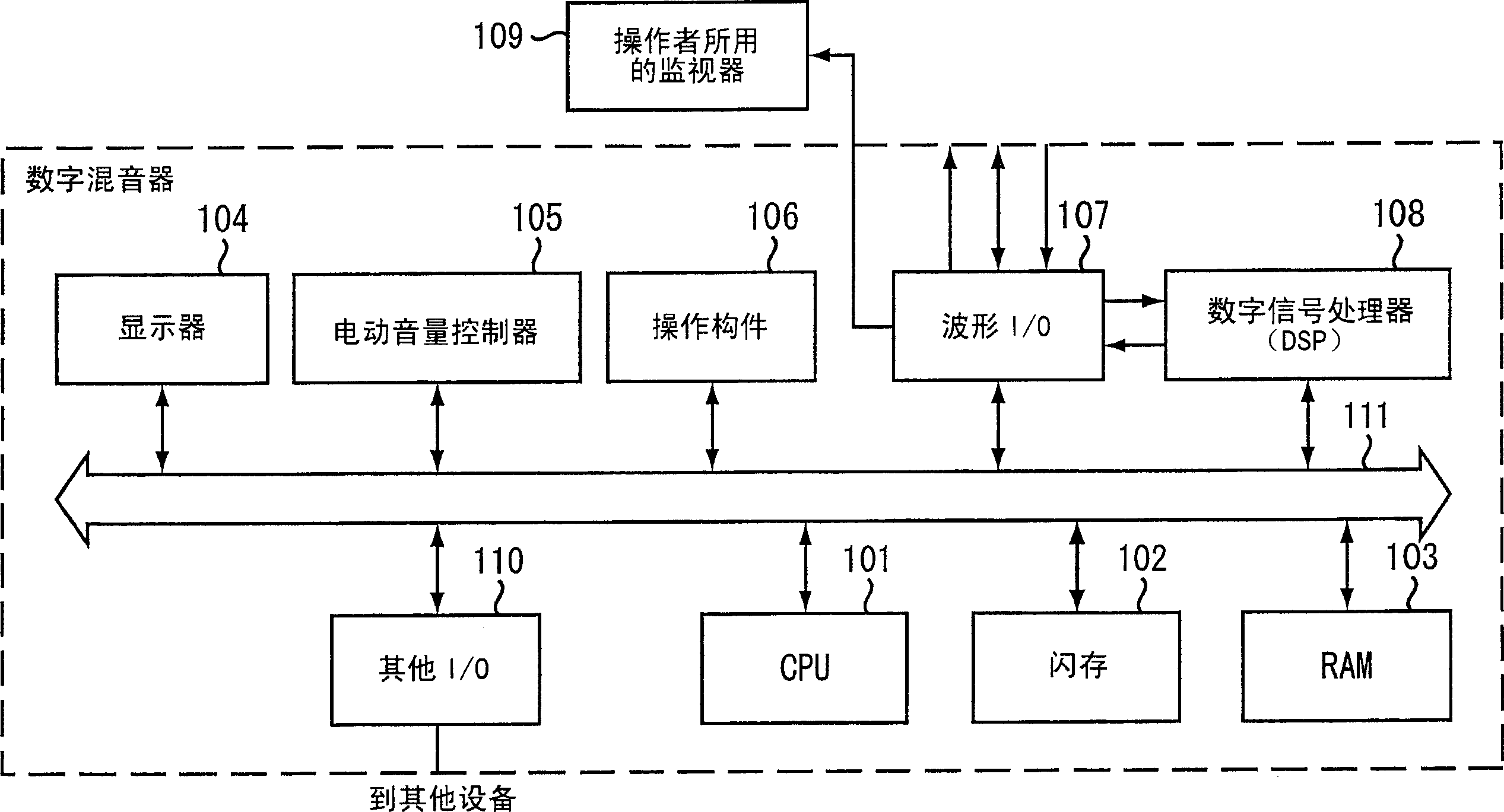
[0038] Hereinafter, embodiments of the present invention will be described with reference to the drawings. figure 1 is a block diagram showing the hardware configuration of a digital mixer to which the mixer of the present invention is applied as an embodiment. The digital mixer is provided with a central processing unit (CPU) 101, a flash memory 102, a random access memory (RAM) 103, a display part 104, an electric volume controller (motor-operated fader) 105, an operating member 106, a waveform input / An output interface (I / O) 107 , a digital signal processor (DSP) 108 , a monitor 109 for an operator, other I / O 110 , and a bus 111 .

[0039] The CPU 101 is a processing unit that controls the mixer as a whole. The flash memory 102 is a nonvolatile memory in which various programs executed by the CPU 101, various data, and the like are stored. The RAM 103 is a volatile memory used as a load area and a work area for programs executed by the CPU 101 . The display 104 is a dis...


PUM


Abstract

In an audio mixing console, a channel strip section is disposed on an operation panel on the basis of a group, which is derived by classifying a plurality of input channels and output channels in groups, and using channel strips provided to the channel strip section, a parameter setting can be performed for each of the channels. In such an audio mixing console, an assignment channel strip section is provided on the center portion of the operation panel for enhancing operability, and the respective channels of the group are each assigned to their corresponding assignment channel strips through operation of a group selection operation member to enable the parameter setting. In a group selection operation section including the group selection operation members on the operation panel, the group selection operation members are disposed in a corresponding manner to the disposition positions of the channel strip sections on the operation panel. Through such disposition, it becomes possible to readily recognize which group of the channel strip section is assigned to the assignment channel strip section.

Description


Claims


Application Information

Patent Timeline
Owner YAMAHA CORP
Learn More