Aerator ejector

A technology of ejector and aerator, which is used in chemical instruments and methods, water aeration, sustainable biological treatment, etc., can solve the problem of restricting aerators, large power consumption, inability to vary power efficiency and mixed outflow velocity, etc. problems, to achieve the effect of increasing the number of aeration times, increasing the degree of oxygenation, and reducing the suspended debris in the pool water

Inactive Publication Date: 2006-09-27
HUAIHAI INST OF TECH
View PDF0 Cites 0 Cited by
  • Summary
  • Abstract
  • Description
  • Claims
  • Application Information

AI Technical Summary

Problems solved by technology

[0007] Due to structural limitations, it is impossible to obtain different power efficiency and mixed outfl

Method used


Image

  • Aerator ejector
  • Aerator ejector

Examples


Embodiment Construction

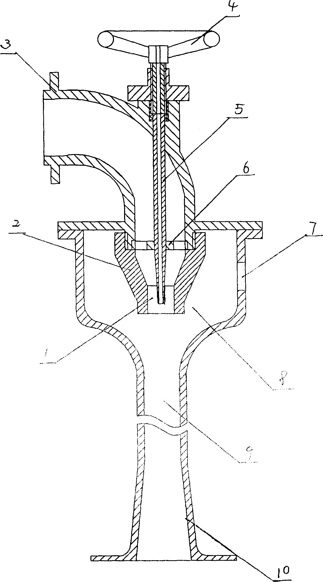
[0017] An aerator jet device, which includes a suction chamber 8, a throat pipe 9, and a diffuser pipe 10. The suction chamber 8 is facing the throat pipe 9 with an inlet for an incoming water flow, and a nozzle 2 is installed at the inlet for the incoming water flow. The water inlet pipe 3 is connected to the outside of the suction chamber 8, an external air inlet 7 is provided on the side wall of the suction chamber 8, and an adjustment pipe 5 is installed axially in the nozzle 2. The adjustment pipe 5 is provided with an inner suction hole, and the inner suction hole The hole wall is required to be very smooth, and the wall thickness of the regulating pipe 5 will ensure that the regulating pipe does not bend substantially when it is impacted by the water flow, and the diameter and wall thickness of the effective regulating section of the regulating pipe 5 located in the spout 1 gradually decreases.

[0018] The water inlet pipe 3 is an elbow connected with the external subme...


PUM


Abstract

The jet device of oxygenator includes an air sucking chamber, a throat pipe and a diffusion pipe. The air sucking chamber has a water flow inlet with nozzle, an outer air inlet on the side wall, a regulating pipe with inner air sucking hole and mounted axially inside the nozzle, and a bending water inlet pipe, a rack set in the water flow inlet. The regulating pipe has the inner end set at the nozzle, the middle part set on the rack and the outer end fixed to the side wall of the bending water inlet pipe. The area ratio between the inner hole cross section of the throat and the annular cross section of the nozzle is 3.5-4.5, reaching optimized air-water mixing effect. The jet device of oxygenator has raised aeration efficiency.

Description

technical field [0001] The invention relates to an aeration equipment for high-density aquaculture, in particular to an aerator jet. Background technique [0002] Aeration equipment is an essential condition for high-density aquaculture. The jet flow aerator uses the jet aeration mechanism to oxygenate water, which has many unique advantages. In addition to being suitable for general aquaculture occasions, it can also solve general problems such as under ice and deep water. The problem of surface oxygenation is difficult to solve. The ejector is the core structure of the jet aerator. In the ordinary self-priming ejector, when the working medium with a certain pressure passes through the nozzle of the ejector, it is ejected from the nozzle at a high speed. A high-speed jet beam is formed, and the jet beam enters the throat mixing chamber after passing through the suction chamber to carry gas. At this time, the suction chamber forms a negative pressure, and...

Claims


Application Information

Patent Timeline
IPC IPC(8): A01K63/04C02F7/00
CPCY02W10/10
Inventor 周建来
Owner HUAIHAI INST OF TECH
Why Eureka
Try Eureka