Bridge expansion joint installation of possessing multidirectional displacement capabilities

A multi-directional displacement and expansion joint technology, applied in bridges, bridge parts, bridge construction and other directions, can solve problems such as corner displacement, bearing fracture, expansion joint device damage, etc., to meet the requirements of tilt displacement, avoid wear, Displacement and panning smooth effects

Active Publication Date: 2006-12-06
徐斌
View PDF0 Cites 4 Cited by
  • Summary
  • Abstract
  • Description
  • Claims
  • Application Information

AI Technical Summary

Problems solved by technology

However, in actual use, under the action of factors such as air temperature and wind force, the beam body will undergo horizontal rotation and twist deformation in the horizontal direction, so that the transverse relative translation will occur between the spanning plate and the beam body, while the traditional modulus and None of the comb-type telescopic devices can meet the needs of this deformation, and the device will cause the vertical and horizontal support beams to be disjointed and fractured, while the comb teeth of the comb-type telescopic device are in rigid contact. In this process, under the action of such lateral deformation and vehicle rolling, the comb teeth are prone to breakage, resulting in damage to the entire expansion joint device
[0003] On the other hand, under the action of vehicle load and air temperature, the vertical corner displacement of the joint plate will also occur, which will seriously damage the entire expansion joint device. For example, for the comb plate type, it is easy to cause the comb teeth to break , while for the modulus type, there will be problems such as support fracture

Method used


Image

  • Bridge expansion joint installation of possessing multidirectional displacement capabilities
  • Bridge expansion joint installation of possessing multidirectional displacement capabilities
  • Bridge expansion joint installation of possessing multidirectional displacement capabilities

Examples


Embodiment Construction

[0029] The present invention will be further described in detail below in conjunction with the accompanying drawings and embodiments.

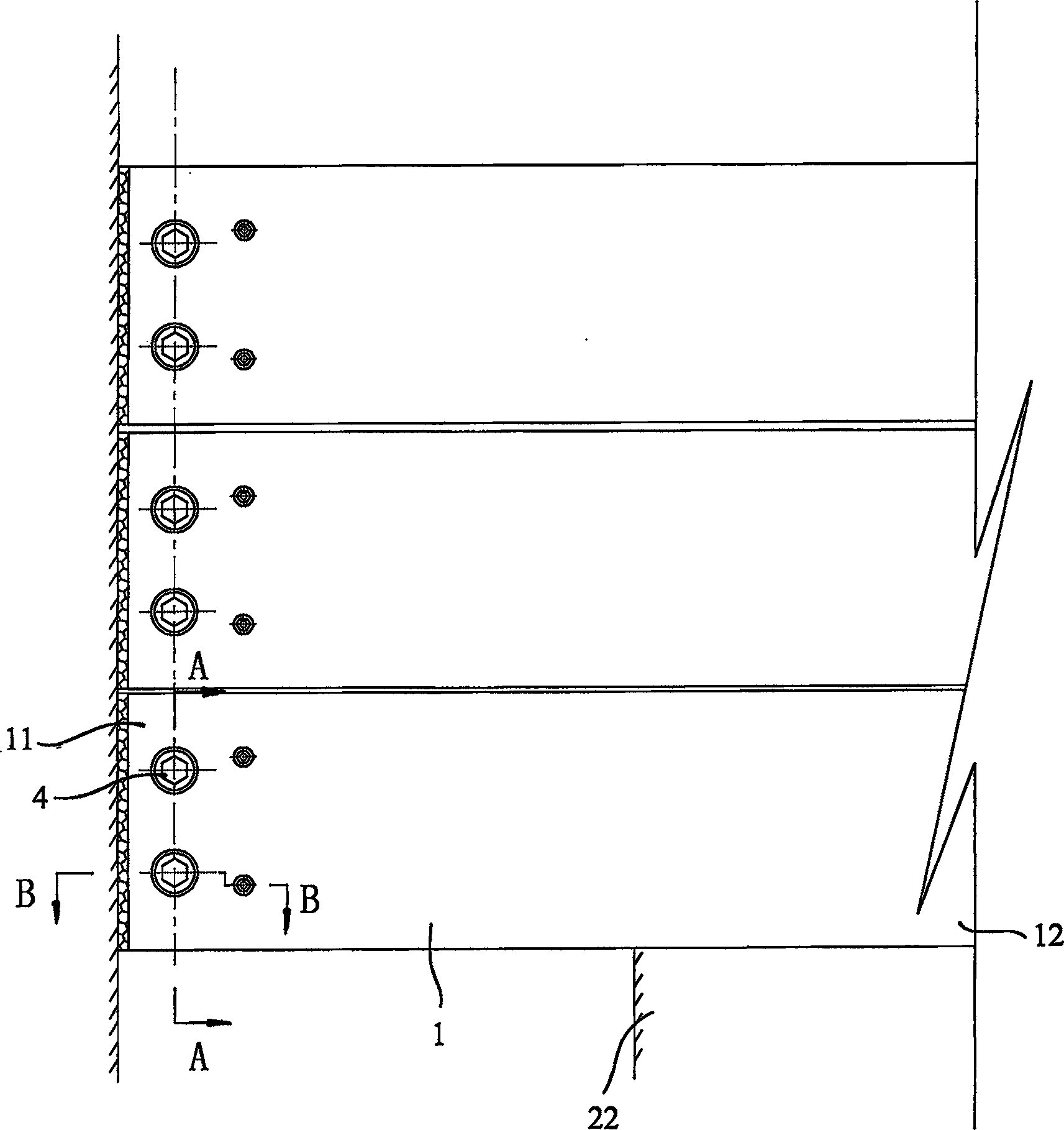
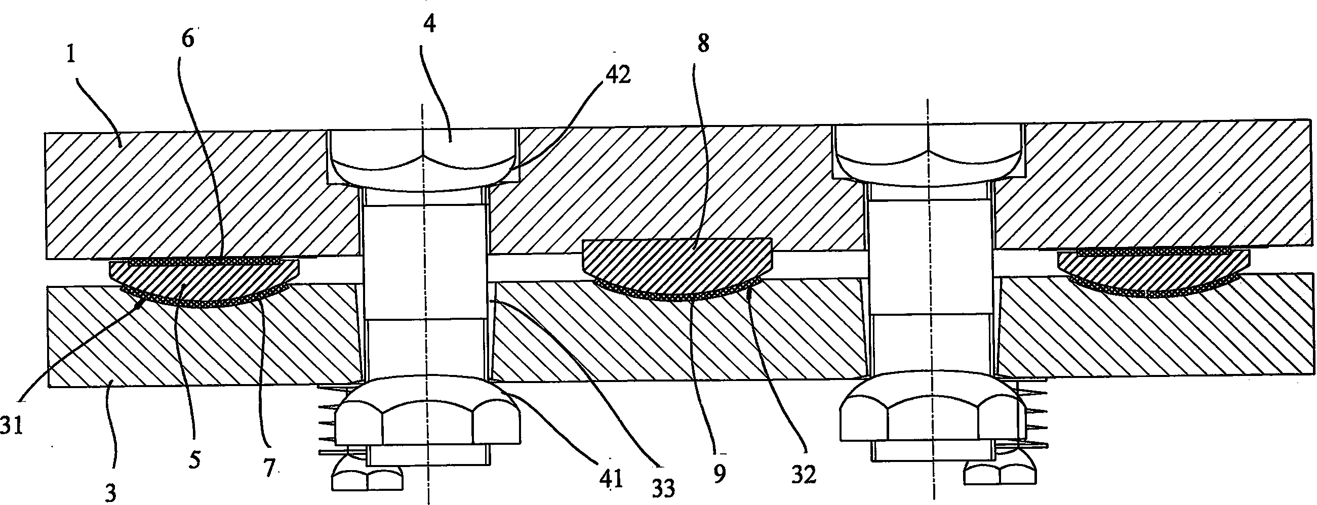
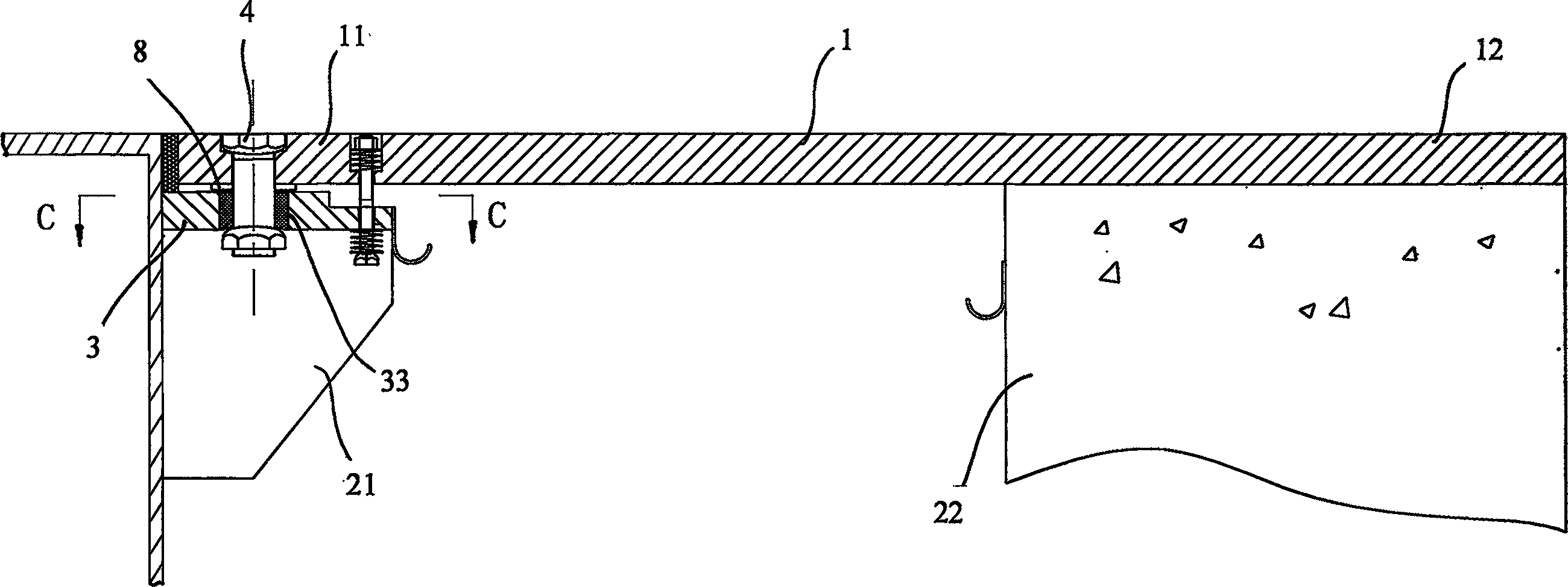
[0030] Such as figure 1 As shown in Figure 6, it is Embodiment 1 of the present invention. The bridge expansion joint device with multi-directional displacement resistance includes a seam-spanning plate 1 arranged on the bridge joint, and the first end 11 of the seam-spanning plate 1 is It is fixed on the first beam body 21 on one side of the bridge gap, while the second end 12 is located on the second beam body 22 on the other side of the bridge gap and can move relative to the second beam body 22. Below the first end 11, there is a lower supporting plate 3 fixed to the first beam body 21, the seam-spanning plate 1 and the lower supporting plate 3 are connected by bolts 4, and between the seam-spanning plate 1 and the lower supporting plate 3 A middle block 5 with a spherical bottom is arranged between, a flat slide plate 6 is arranged on th...


PUM


Abstract

A bridge expansion joint device with multidirectional shift ability is prepared as fixing the first end of over joint plate on the first beam, placing the second end on the second beam and enabling said plate to relatively move on said beam, setting bottom support board fixed on the first beam under the first end of said plate, connecting said plate with bottom support board by bolt, setting intermediate block with spherical surface at bottom between said plate and said board, setting planar sliding plate above intermediate block being set with spherical sliding plate at its bottom.

Description

technical field [0001] The invention relates to a bridge expansion joint device, in particular to a bridge expansion joint device with multidirectional displacement capability. Background technique [0002] In the existing bridge expansion joint devices, no matter it is a comb-type plate type or a welded type, a spanning plate is arranged on the bridge expansion joint, and one end of the spanning plate is fixed on the beam body on one side of the bridge joint, and the other One end is located on the beam body on the other side of the bridge expansion joint and can move relative to the beam body. However, in actual use, under the action of factors such as air temperature and wind force, the beam body will undergo horizontal rotation and twist deformation in the horizontal direction, so that the transverse relative translation will occur between the spanning plate and the beam body, while the traditional modulus and None of the comb-type telescopic devices can meet the needs ...

Claims


Application Information

Patent Timeline
Patent Type & Authority Applications(China)
IPC IPC(8): E01D19/06
Inventor 徐斌
Owner 徐斌
Why Eureka
Try Eureka