Method for manufacturing liquid crystal display device

A technology for a liquid crystal display and a manufacturing method, which is applied to static indicators and other directions, can solve the problems of display quality degradation and polymer residues, and achieve the effect of improving display quality.

Inactive Publication Date: 2006-12-13
INNOLUX CORP
View PDF1 Cites 5 Cited by
  • Summary
  • Abstract
  • Description
  • Claims
  • Application Information

AI Technical Summary

Problems solved by technology

However, the prior art method firstly mixes the liquid crystal and the polymer monomer, and then separates the phases by lighting. This method easily causes too much polymer to remain in the liquid crystal display area, resulting in a decrease in display quality.

Method used


Image

  • Method for manufacturing liquid crystal display device
  • Method for manufacturing liquid crystal display device
  • Method for manufacturing liquid crystal display device

Examples


Embodiment Construction

[0035] The following diagrams and preferred embodiments are used to describe the present invention in more detail.

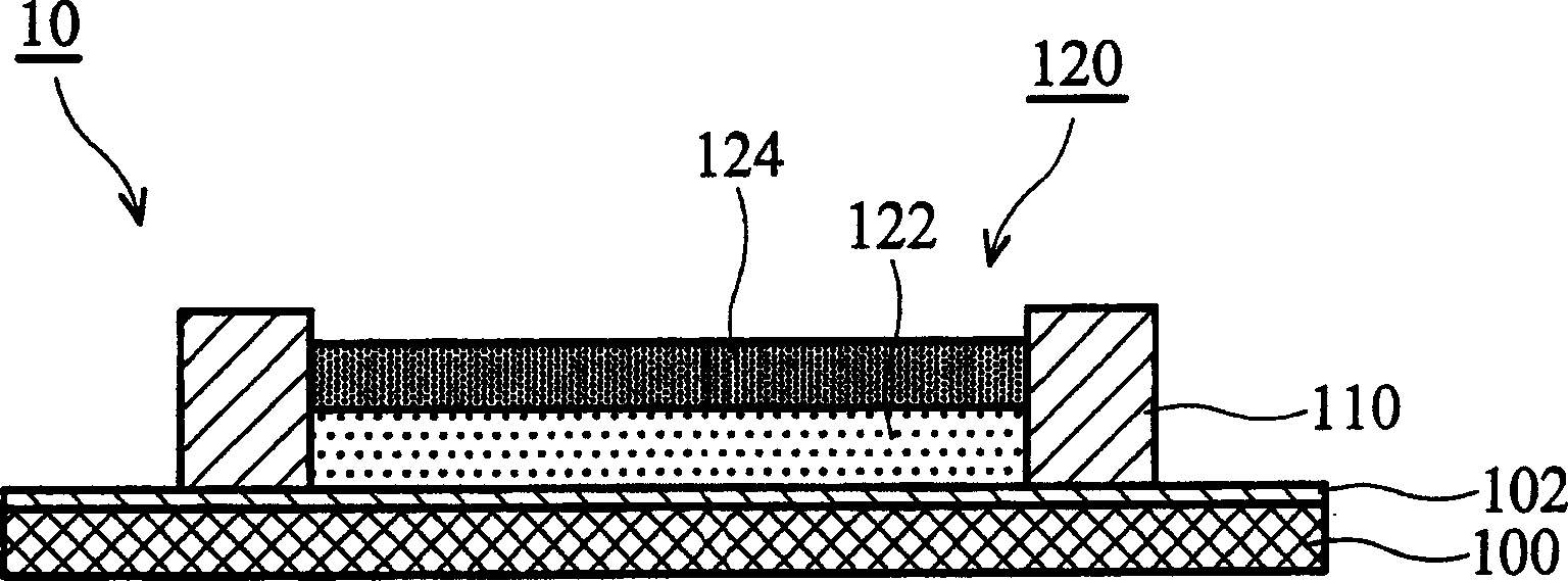
[0036] figure 2 It is a liquid crystal display that shows a single-substrate structure formed by combining inkjet method and liquid crystal / polymer phase separation technology according to an embodiment of the present invention. see figure 2 , a liquid crystal display 10 with a single-substrate structure includes a substrate 100 with a first electrode layer thereon. An alignment layer 102 is disposed on the substrate 100 with the first electrode layer. A patterned protrusion structure 110 is disposed on the substrate 100 to be divided into a plurality of pixel regions 120 . A liquid crystal layer 122 is filled in each pixel region 120 . A polymer material layer 124 is disposed in each pixel area 120 and located on the liquid crystal layer 122 .

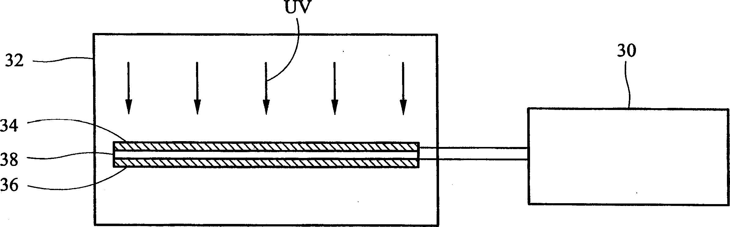
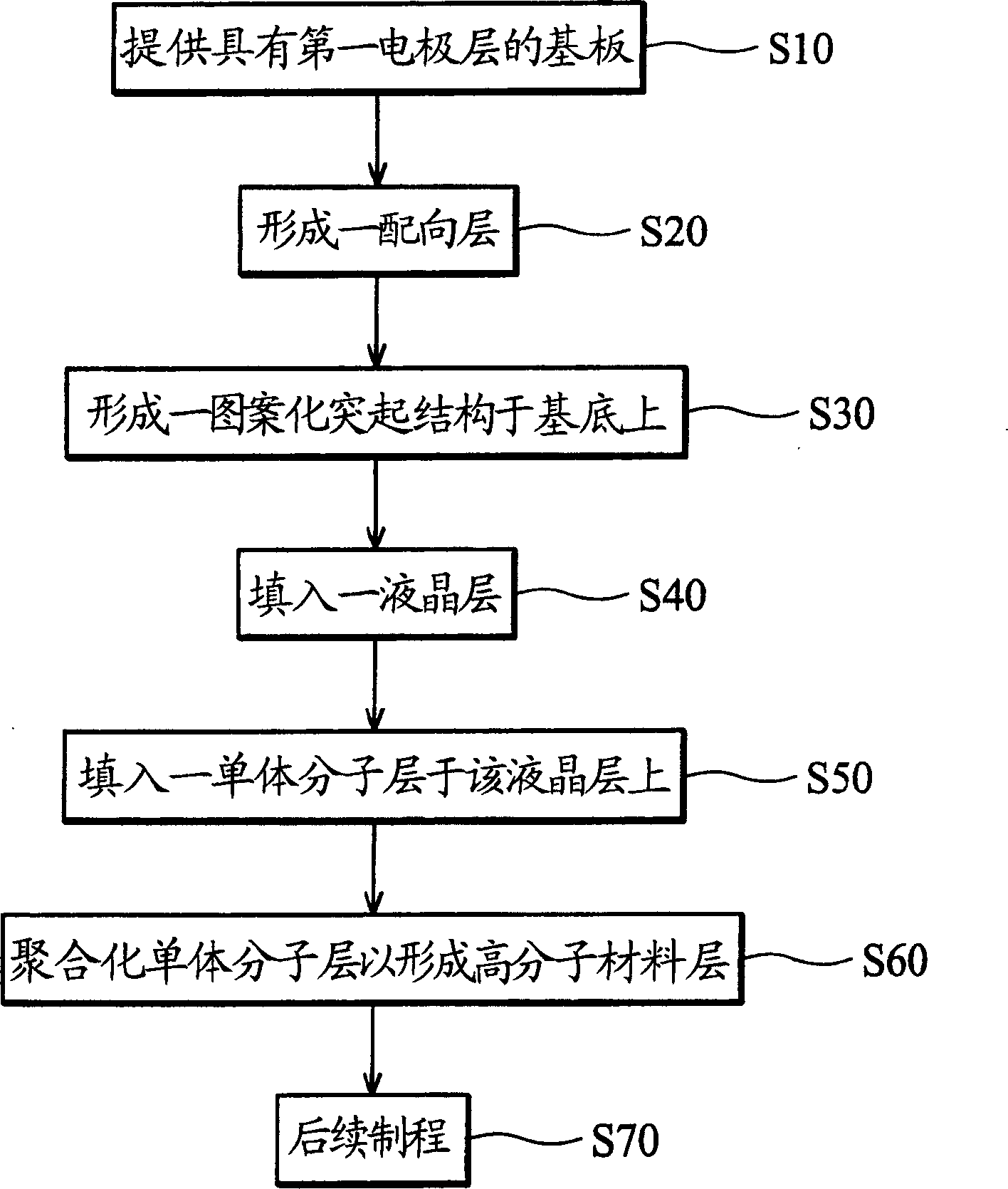
[0037] image 3 It is a flowchart showing a method of manufacturing the liquid crystal display 10 . First, a...


PUM


Abstract

The invention provides a method for making liquid crystal display. The method comprises providing a base board with a first electrode on it; forming a graphical projection structure on the base board for separating it into plural pixel areas; filling a liquid crystal layer into each pixel area; filling a monomer molecule layer into each pixel area on the liquid crystal layer; aggregating the monomer molecule layer to be a high polymer material layer and separating with the liquid crystal layer. The inventive method has the advantages of being able to improve the display quality of single base board structure.

Description

technical field [0001] The invention relates to a method for manufacturing a liquid crystal display, in particular to a method for manufacturing a liquid crystal display by using an inkjet method and a phase separation technology. Background technique [0002] Liquid crystal displays (LCDs) have many advantages, such as small size, light weight, low power consumption, and so on. Therefore, LCDs have been widely used in portable computers, mobile phones and other electronic products. In other words, liquid crystal display technology is heading towards the field of being light, thin and easy to carry. For example, Philips (Philips) proposed at the 2004 Society for Information Display (SID) annual meeting that in order to improve the bendability of flexible displays, the first condition should be to reduce the overall component thickness. In other words, if the thickness of the element reaches more than 400 μm, the flexibility of the display will change from flexible to benda...

Claims


Application Information

Patent Timeline
Patent Type & Authority Applications(China)
IPC IPC(8): G02F1/133
Inventor 沙益安廖奇璋王兴龙丁兆民
Owner INNOLUX CORP
Why Eureka
Try Eureka