

Inductor and base therefor
A technology of inductors and fitting parts, applied in the directions of inductors, fixed inductors, fixed signal inductors, etc., can solve the problems of increasing the defective rate of inductors, time-consuming and cost-consuming, magnetic leakage, etc., and improve the comprehensive manufacturing process. Ability index, improve electromagnetic shielding, reduce electromagnetic interference effect
- Summary
- Abstract
- Description
- Claims
- Application Information
AI Technical Summary
Problems solved by technology
Method used
Image

Examples
Embodiment Construction
[0020] The inductor and its base according to a preferred embodiment of the present invention will be described below with reference to related drawings.
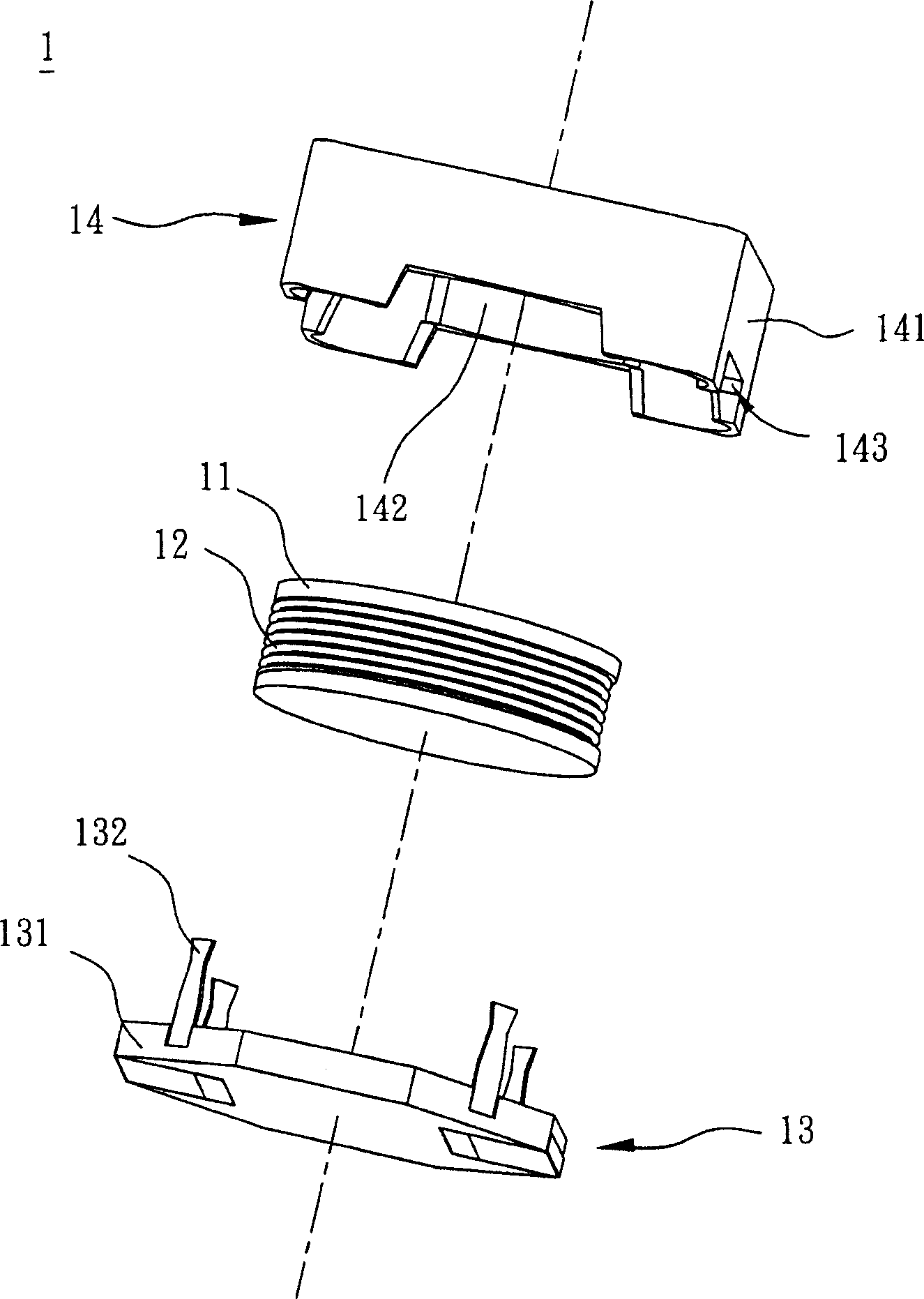
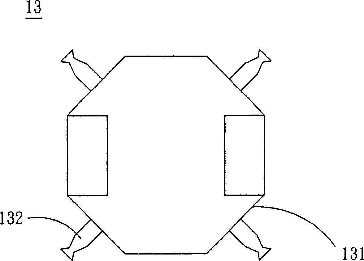
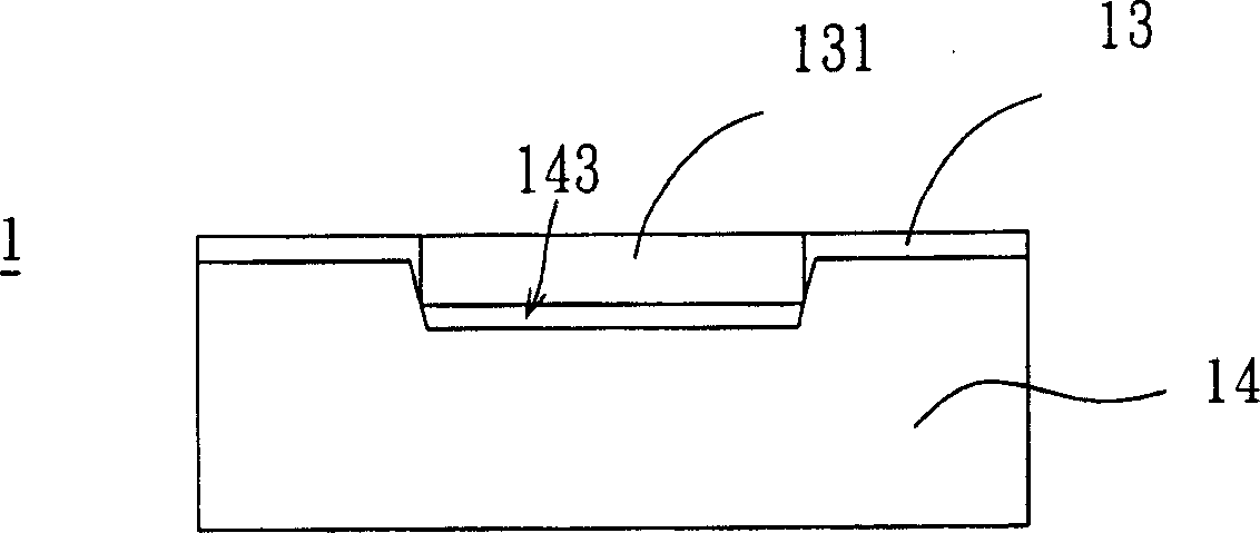
[0021] Please also see Figure 4 and Figure 5A , Figure 4 is a three-dimensional exploded view of the inductor of the present invention, and Figure 5A It is a schematic diagram of the base of the inductor of the present invention. The inductor 5 of the preferred embodiment of the present invention includes an iron core 51 , a coil 52 , a hat-shaped iron core 53 and a base 4 . The iron core 51 is made of a drum-shaped magnetic material, and the coil 52 is wound on the iron core 51 . The base 4 is connected to one end of the iron core 51 , and the connecting pins 46 of the base 4 are bent toward the iron core 51 , and the wire ends of the coil 52 can be wound on each connecting pin 46 .
[0022] like Figure 5A As shown, the base 4 is approximately octagonal, has two opposite horizontal sides 41, two opposite vertica...
PUM
 Abstract
Description
Claims
Application Information