Additive manufacturing equipment and wind field structure thereof

An additive manufacturing and equipment technology, applied in the field of additive manufacturing equipment and its wind field structure, can solve the problems of reduced performance consistency of the formed workpiece, unqualified performance of the formed workpiece, and attenuation of the direction of movement of the protective airflow, so as to improve the molding, The effect of improving performance consistency

Pending Publication Date: 2021-11-09
HUNAN FARSOON HIGH TECH CO LTD
View PDF0 Cites 1 Cited by
  • Summary
  • Abstract
  • Description
  • Claims
  • Application Information

AI Technical Summary

Problems solved by technology

[0004] With the increase in the demand for large-sized molding workpieces, the volume of the equipment will also become larger and larger. The disadvantages of the combination of the traditional single blowing port and suction port will be magnified. The increase in the forming area will make the protective airflow generated by the traditional structure in the direction of movement. The greater attenuation on the surface will cause the working powder to be blown away due to too high wind speed during the fusion molding process, or the spatter generated cannot be taken away from the working area due to too low wind speed, which will greatly reduce the consistency of the performance of the formed workpiece , in severe cases, it may lead to unqualified performance of the molded workpiece and scrap it

Method used


Image

  • Additive manufacturing equipment and wind field structure thereof
  • Additive manufacturing equipment and wind field structure thereof
  • Additive manufacturing equipment and wind field structure thereof

Examples


Embodiment Construction

[0028] In order to make the purpose, technical solution and advantages of the present application clearer, the present application will be further described in detail below in conjunction with the accompanying drawings and embodiments. It should be understood that the specific embodiments described here are only used to explain the present application, and are not intended to limit the present application.

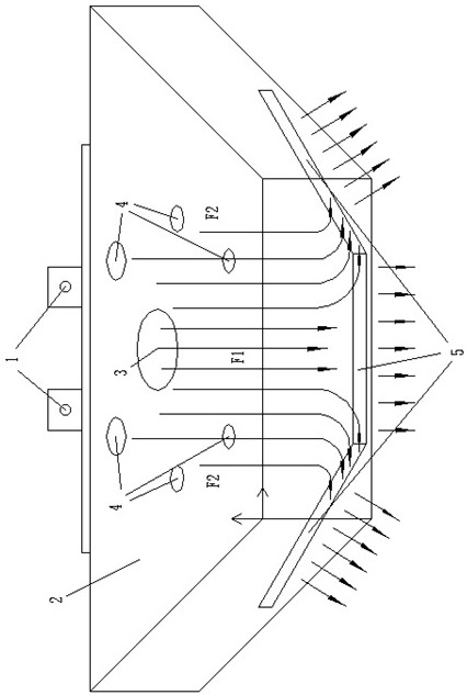
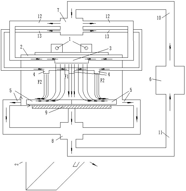
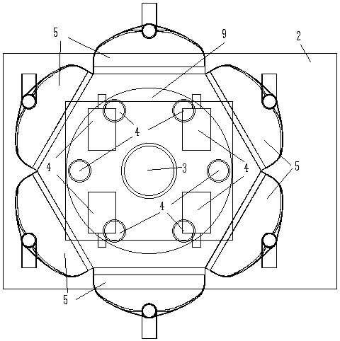
[0029] Such as Figure 1 to Figure 4 As shown, the present invention provides a wind field structure for additive manufacturing equipment, including at least one first air intake duct 3, two or more second air intake ducts 4, several suction ducts 5 and fans 6 , the at least one first air inlet pipe 3 is arranged in the top central area of ​​the working chamber 2 of the additive manufacturing equipment, and is used to input the gas output by the blower 6 into the working chamber 2, forming a secondary gas flow from the working chamber 2 in the working chamber 2 The top fl...


PUM


Abstract

The invention relates to additive manufacturing equipment and a wind field structure thereof. The wind field structure comprises at least one first gas inlet pipeline, two or more second gas inlet pipelines, a plurality of gas suction pipelines and a fan, wherein the first gas inlet pipeline is arranged in the central area of the top of a working cavity of the additive manufacturing equipment and used for inputting gas output by the fan into the working cavity, the second gas inlet pipelines are arranged around the first gas inlet pipeline serving as a center and used for inputting gas output by the fan into the working cavity, the gas suction pipelines are arranged at the bottom of the working cavity, sequentially distributed on the periphery of a working plane for additive manufacturing and used for sucking the gas in the working cavity and conveying the gas to the fan, and pipe openings, used for sucking the gas, of the gas suction pipelines are higher than the working plane so that full-breadth annular circulating gas flow can be formed above the working plane. According to the wind field structure, the full-breadth annular circulating gas flow is formed above the working plane, so that the performance consistency of large-size printed workpieces is greatly improved.

Description

technical field [0001] The present application relates to the technical field of additive manufacturing, in particular to an additive manufacturing equipment and its wind field structure. Background technique [0002] Additive manufacturing technology is an advanced manufacturing technology with distinctive features such as digital manufacturing, high flexibility and adaptability, direct CAD model drive, fast speed, and rich and diverse material types. tooling mold, so the application range is very wide. Selective Laser Melting (SLM) is one of the additive manufacturing technologies that has developed rapidly in recent years. It uses powder materials as raw materials and uses laser to scan the cross-section of a three-dimensional entity layer by layer to complete prototype manufacturing. It is not affected by the shape of the part. The complexity is limited, no tooling is required, and the application range is wide. The basic process of the selective laser melting process ...

Claims


Application Information

Patent Timeline
IPC IPC(8): B22F12/70B33Y30/00
CPCB22F12/70B33Y30/00Y02P10/25
Inventor 谢洋生刘鑫炎潘良明肖建军苗俊杰谭振中
Owner HUNAN FARSOON HIGH TECH CO LTD
Why Eureka
Try Eureka