A Calculation Method of Trimming Points Based on Binocular Vision

A technology of binocular vision and calculation method, which is applied in the directions of calculation, image analysis, image enhancement, etc., and can solve the problems of low precision, the detection accuracy of precision instruments, and the inability to fully describe the geometric characteristics of spatial boundaries, etc.

Active Publication Date: 2021-03-16
易思维(杭州)科技有限公司
View PDF4 Cites 0 Cited by
  • Summary
  • Abstract
  • Description
  • Claims
  • Application Information

AI Technical Summary

Problems solved by technology

[0002] With the development of automation technology and the improvement of social productivity, the manufacturing industry has become more and more strict about product quality control. The basic principles of improving manufacturing quality can be summarized into two categories: 1. The method of avoiding errors-this method uses Processing equipment, advanced control structure and high-reliability sensor detection mechanism can fundamentally improve the quality of processed parts, but this method is complicated to operate and expensive, and there is no complete real-time solution at present; 2. Error compensation Method - This method is to use modern testing technology, new statistical tolerance method combined with existing engineering control and statistical control methods to study product size distribution characteristics, analyze the processing status of mold fixtures, and then control and adjust them. This method has attracted more and more attention, and the key technology to implement this method is measurement, which can obtain effective data of the measured object, thus providing the basis for subsequent control methods
[0003] Among the many measured features, trimming point is an important category to be tested. Taking the car body in white as an example, whether the position of trimming point is accurate or not is directly related to the straightness of the edge of the workpiece. The basis for meeting the requirements; the traditional inspection sample rack is a widely used inspection tool in the 1970s. This method is low in cost, but the inspection speed is slow and the accuracy is low (about 0.1mm), which cannot meet the inspection accuracy required by precision instrument manufacturing; Another detection method is to use a three-coordinate measuring machine (CMM) for trimming point detection. Although this method has high precision, the measurement speed is very slow. For space boundary points, only a limited number of points can be measured, and it is impossible to fully describe the space boundary. Geometric dimension features, and the measurement process requires manual intervention, and the measurement results need to be compensated for probe damage and probe radius

Method used


Image

  • A Calculation Method of Trimming Points Based on Binocular Vision
  • A Calculation Method of Trimming Points Based on Binocular Vision
  • A Calculation Method of Trimming Points Based on Binocular Vision

Examples


Embodiment Construction

[0029] The technical solutions of the present invention will be described in detail below with reference to the accompanying drawings and examples.

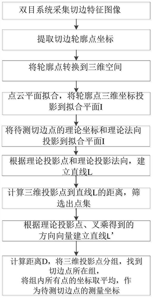
[0030] A cutting point calculation method based on binocular visual, including the following steps:

[0031] 1) Use the binocular visual measurement system to collect the left and right grayscale images of the cutting edge characteristics;

[0032] 2) For the left, right images, the graphic filter, two-value image, edge detection and other image pretreatment, extract the two-dimensional point coordinate N of the cutofline edge of the left and right images N t , T = 1, 2, ... s; s is the number of two-dimensional points of the contour edge edge;

[0033] 3) Use the polar match method to convert the cut-edge profile points in the left and right images to the three-dimensional point coordinate data of the cut-edge profile;

[0034] 4) Using the three-dimensional scanner to obtain the three-dimensional dot cloud of the plane of the measu...


PUM


Abstract

The invention discloses a trimming point calculation method based on binocular vision. The trimming point calculation method comprises the following steps: carrying out binocular vision measurement toobtain a trimming three-dimensional coordinate; carrying out plane fitting to obtain a plane I, and projecting the trimmed three-dimensional coordinate to the fitting plane I to obtain an Nj; projecting the theoretical coordinates and the theoretical normal of the trimming point to a plane I, and establishing a straight line L; calculating the distance from Nj to the straight line L to obtain Nj'; carrying out cross multiplication to obtain a vector n '', and establishing a straight line L '; calculating the distance D from Nj to L' in the direction n'of the theoretical projection normal direction, and dividing the three-dimensional projection points Nj into N groups according to the value D and the preset step length; selecting a group with the maximum D value and the intra-group pointnumber larger than m as a group where the trimming point is located; averaging the coordinates of all the three-dimensional projection points in the group where the trimming points are located to obtain trimming point measurement coordinates. According to the method, the measurement coordinate precision can reach tens of micrometers, the measurement time is millisecond, and the detection requirements of the precision machining and manufacturing industry such as the automobile industry can be met.

Description

Technical field [0001] The present invention relates to the field of feature detection, and more particularly to a cutting point calculation method based on bicomputer visual. Background technique [0002] With the development of automation technology, the improvement of social productivity is increasingly strict, and the basic principles of product quality are increasing, and the basic principles of manufacturing quality can be concatenated into two categories: 1. Avoid errors - this method utilizes high precision Processing equipment, advanced control structure and high reliability sensor detection mechanism fundamentally improving the quality of the machined parts, but this method is complex, costly, currently has no complete real-time scheme; 2. Error compensation Method - This method is to use modern test technology, the new statistological tolerance method combined with existing engineering control and statistical control methods, study product size distribution characteris...

Claims


Application Information

Patent Timeline
Patent Type & Authority Patents(China)
IPC IPC(8): G06T7/11G06T7/00G06T5/00G06T3/00G06T7/70G01B11/00G06T7/13
CPCG01B11/002G06T3/0012G06T5/002G06T7/0004G06T2207/30168G06T7/11G06T7/13G06T7/70
Inventor 魏志博邢威张楠楠
Owner 易思维(杭州)科技有限公司
Why Eureka
Try Eureka