Satellite broadcasting system
A technology of satellite broadcasting and satellite, which is applied in the field of satellite broadcasting system and can solve problems such as drivers falling asleep
- Summary
- Abstract
- Description
- Claims
- Application Information
AI Technical Summary
Problems solved by technology
Method used
Image

Examples
no. 1 approach
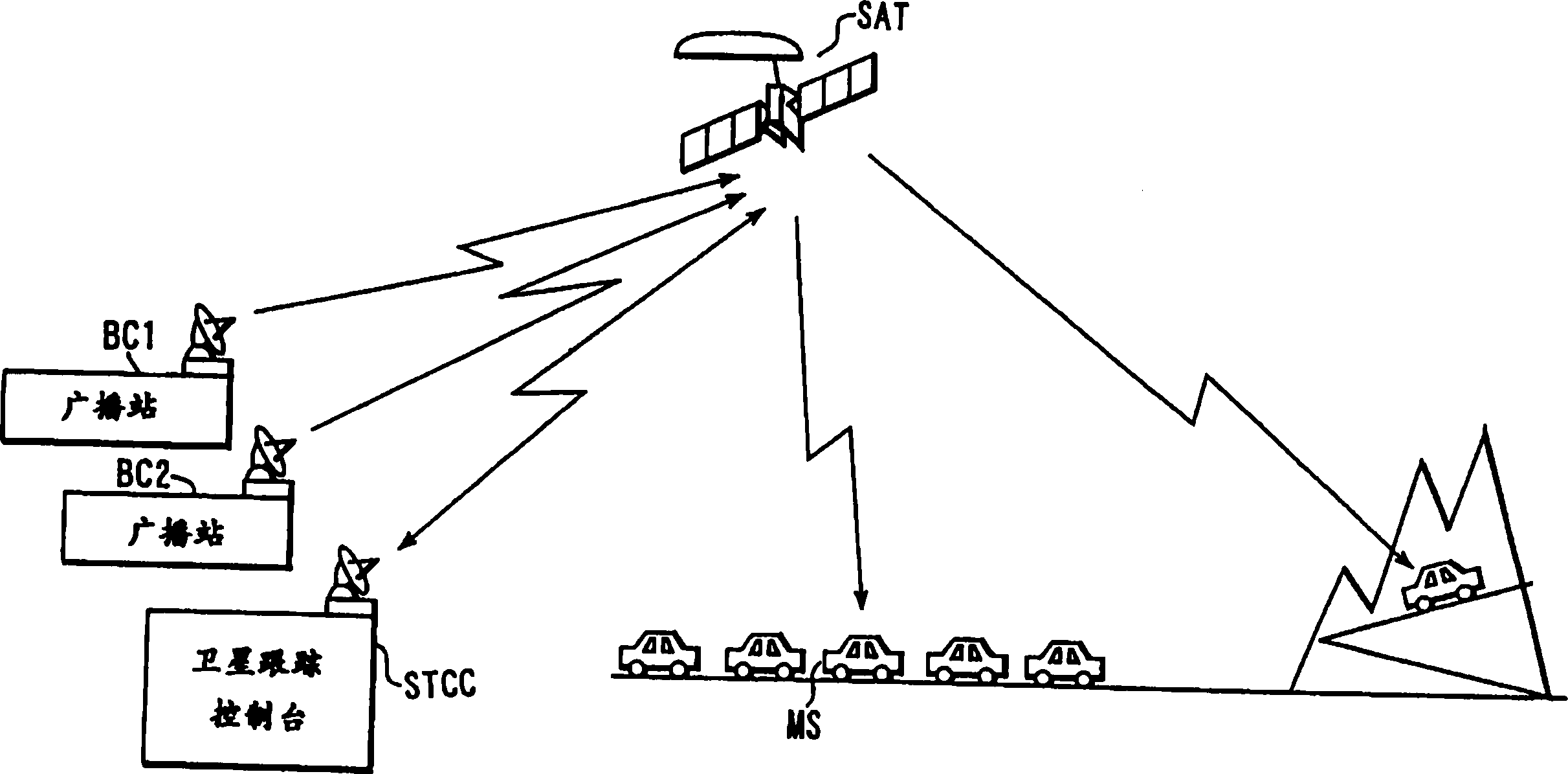
[0100] figure 1 is a schematic diagram illustrating the satellite broadcasting system according to the first embodiment of the present invention.
[0101] This satellite broadcasting system consists of terrestrial broadcasting stations (VSAT) BC1 and BC2 or feeder link stations used as transmitters for ground stations, a geostationary satellite SAT used as satellite repeater, and a satellite tracking console STCC.
[0102] Terrestrial broadcast stations (VSAT) BC1 and BC2 or feeder-link stations, each transmitting broadcast stations in the Ka-band (26.5 to 40GHz) or Ku-band (12.5 to 18GHz) via uplink transmission channels to this geostationary satellite SAT Program information produced and edited by (broadcaster).
[0103] The geosynchronous satellite SAT is equipped with a Ka-band or Ku-band antenna with a diameter of 2.5m and a S-band (eg 2.6GHz) antenna with a diameter of 15m. The broadcast signal multiplexed and transmitted by one of these broadcast stations (VSAT) BC1 ...
no. 2 approach
[0112] In the second embodiment of the present invention, the geostationary satellite SAT detects the spread code phase difference between the channels of a CDM broadcast signal from each terrestrial broadcast station BC1 or BC2, and according to the detection result, the spread between the channels The code phases are matched and a signal is then sent to the broadcast receiver MS.
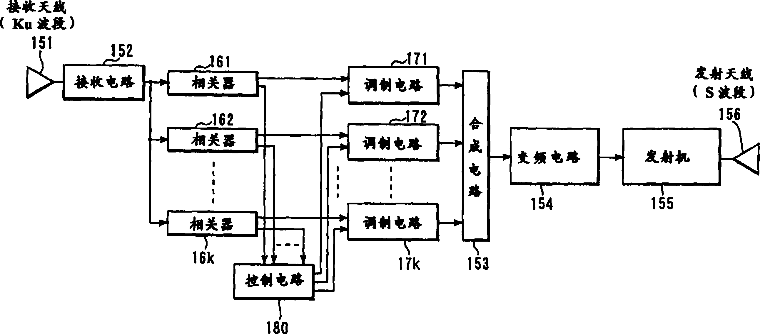
[0113] image 3 is a block diagram illustrating the configuration of the geostationary satellite SAT according to the second embodiment. refer to image 3 , a CDM broadcast signal sent by the terrestrial broadcast station BC1 or BC2 is received by the Ku-band receiving antenna 151 and then input to the receiving circuit 152 . The CDM broadcast signal is amplified with low noise, down-converted to an IF signal, and then distributed to k correlators 161 to 16k. The number of correlators 161 to 16k is set according to the total number k of channels multiplexed / transmitted by the terrestrial broadc...
no. 3 approach
[0120] In the third embodiment of the present invention, when the terrestrial broadcast station BC1 or BC2 generates a CDM broadcast signal and transmits the CDM broadcast signal, it detects the spread code phase difference between channels, and the phase difference information is multiplexed into The CDM broadcast signal is then transmitted. When selectively receiving one of the channels of the CDM broadcast signal arriving through the geostationary satellite SAT, the broadcast receiver MS adjusts the chip phase (chip phase) of the spreading code based on the phase difference information received together with the CDM broadcast signal. phase), and selectively despread the frequency spectrum of the broadcast signal of each channel using the spreading code, thereby reproducing the broadcast signal.
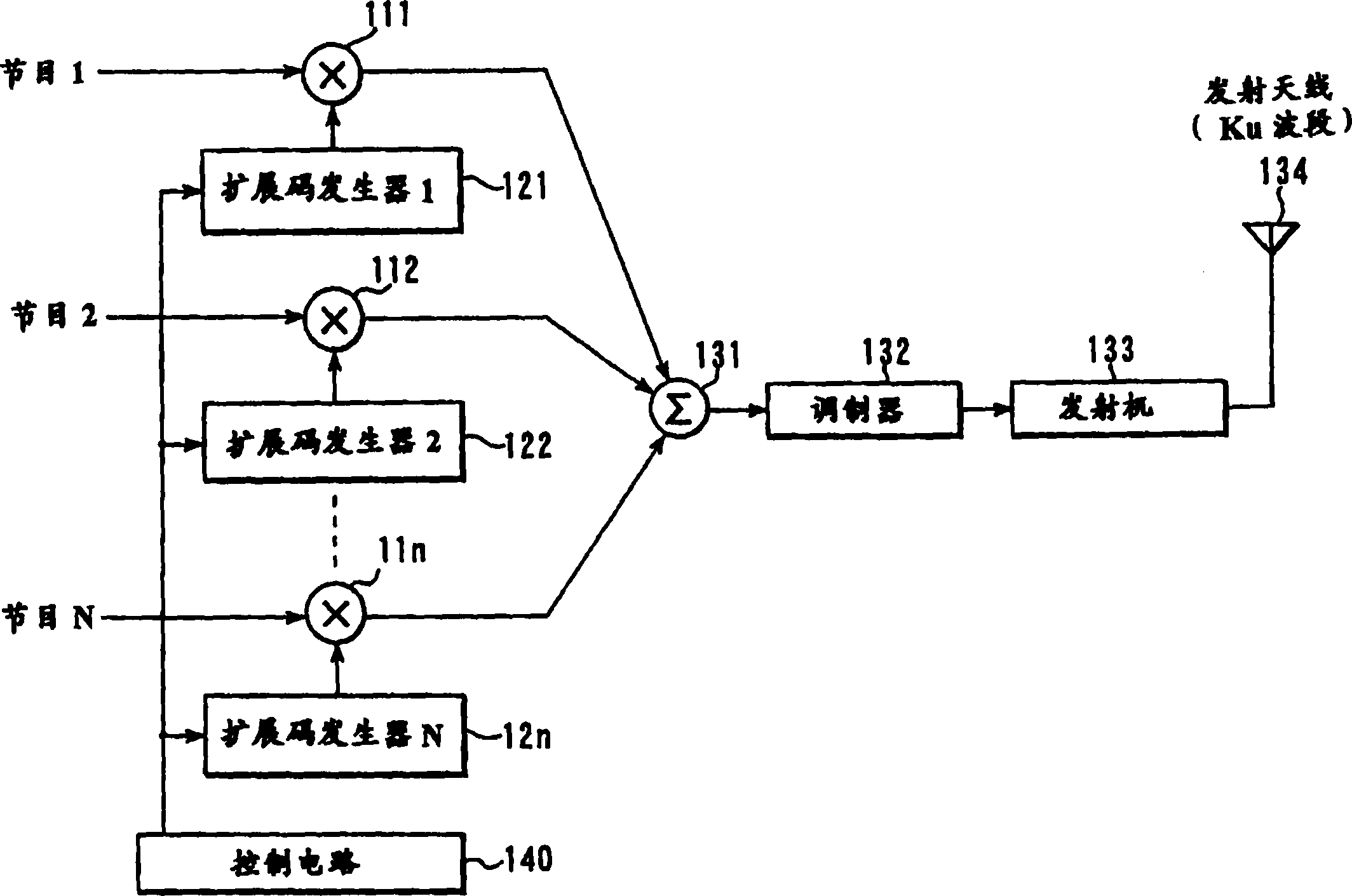
[0121] Figure 4 is a block diagram illustrating the configuration of the transmission section of each of the terrestrial broadcasting stations BC1 and BC2 according to this embod...
PUM
| Property | Measurement | Unit |
|---|---|---|
| Diameter | aaaaa | aaaaa |
| Diameter | aaaaa | aaaaa |
| Diameter | aaaaa | aaaaa |
Abstract
Description
Claims
Application Information
 - R&D Engineer
- R&D Manager
- IP Professional
- Industry Leading Data Capabilities
- Powerful AI technology
- Patent DNA Extraction
Browse by: Latest US Patents, China's latest patents, Technical Efficacy Thesaurus, Application Domain, Technology Topic.
© 2024 PatSnap. All rights reserved.Legal|Privacy policy|Modern Slavery Act Transparency Statement|Sitemap