Fiber to the home (FTTH) multimedia access system with reflection PON

a multimedia access system and fiber-to-the-home technology, applied in the field of broadband multimedia communication systems, can solve the problems of limiting the ability to receive and transmit high-speed data signals along with traditional quality voice signals, access parts of the network are not well matched to the type of information, and user demand to shi

Inactive Publication Date: 2002-05-30
ADVANCED FIBER ACCESS CORP
View PDF22 Cites 236 Cited by
  • Summary
  • Abstract
  • Description
  • Claims
  • Application Information

AI Technical Summary

Benefits of technology

[0018] The present invention provides many advantages, such as: (1) provides an inexpensive, easy-to-service architecture enabling the bi-directional communication of voice, high-speed data, CATV and DBS multi-media services within the local-loop between a central office terminal and a plurality of subscribers; (2) provides a passive optical network (PON) architecture with no intermediate electronics to service; (3) provides a data transmission protocol including variable-length packets, guard time interval, a common packet structure for all types of information, multiple queues to prioritize different types of data during multiplexing, an addressing scheme that is used to differentiate the different types of multi-media data during demultiplexing, and a bit error detection mechanism; (4) enables the fragmentation of packets across two or more time slots in the data protocol; (5) provides 8B10B coding in order to (i) provide additional bit information to assist in the detection of bit errors, (ii) delineate the boundary between adjacent data packets, and (iii) provide known control data when no information is being transmitted; (6) the system includes a collision avoidance mechanism having a downstream control signal that tells each HNU what time slot they are to communicate on within the upstream TDMA channel; (7) provides high-speed, symmetrical PPPOE data transport; (8) the architecture is easily scaled to other types of services and services operating at higher data rates, such as 100Base-T Ethernet; (9) provides a mechanism for prioritizing voice traffic; (10) low latency; (11) provides bi-directional optical transmission using the same wavelength on a single fiber; and (12) provides an advanced echo-cancellation circuit.

Problems solved by technology

The basic problem with transporting data traffic over this voice-centric network, and in particular the local loop access part of the network, is that it is optimized for voice traffic, not data.
The voice-centric structure of the access network limits the ability to receive and transmit high-speed data signals along with traditional quality voice signals.
Simply put, the access part of the network is not well matched to the type of information it is now primarily transporting.
As users demand higher and higher data transmission capabilities, the inefficiencies of the present access network will cause user demand to shift to other mediums of transport for fulfillment, such as satellite transmission, cable distribution, wireless services, etc.
These prior art DLC and FTTC systems suffer from several disadvantages.
First, these systems are costly to implement and maintain due to the need for sophisticated signal processing, multiplexing / demultiplexing, control, management and power circuits located in the HDT and the ONUs.
Purchasing, and then servicing this equipment over its lifetime has created a large barrier to entry for many local loop service providers.
Scalability is also a problem with these systems.
Although these systems can be partially designed to scale to future uses, data types and applications, they are inherently limited by the basic technology underpinning the HDT and the ONUs.
Absent a wholesale replacement of the HDT or the ONUs (a very costly proposition), these DLC and FTTC systems have a limited service life due to the design of the intermediate electronics in the access loop.

Method used


Image

  • Fiber to the home (FTTH) multimedia access system with reflection PON
  • Fiber to the home (FTTH) multimedia access system with reflection PON
  • Fiber to the home (FTTH) multimedia access system with reflection PON

Examples


first embodiment

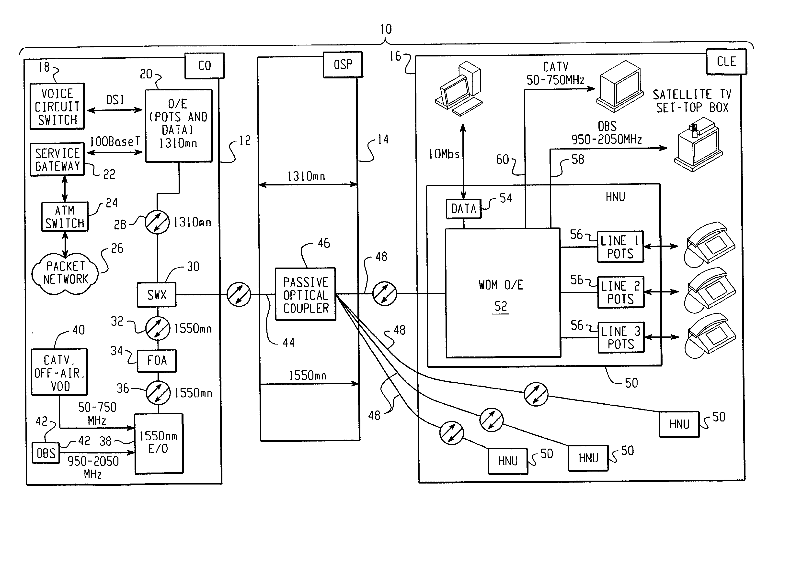
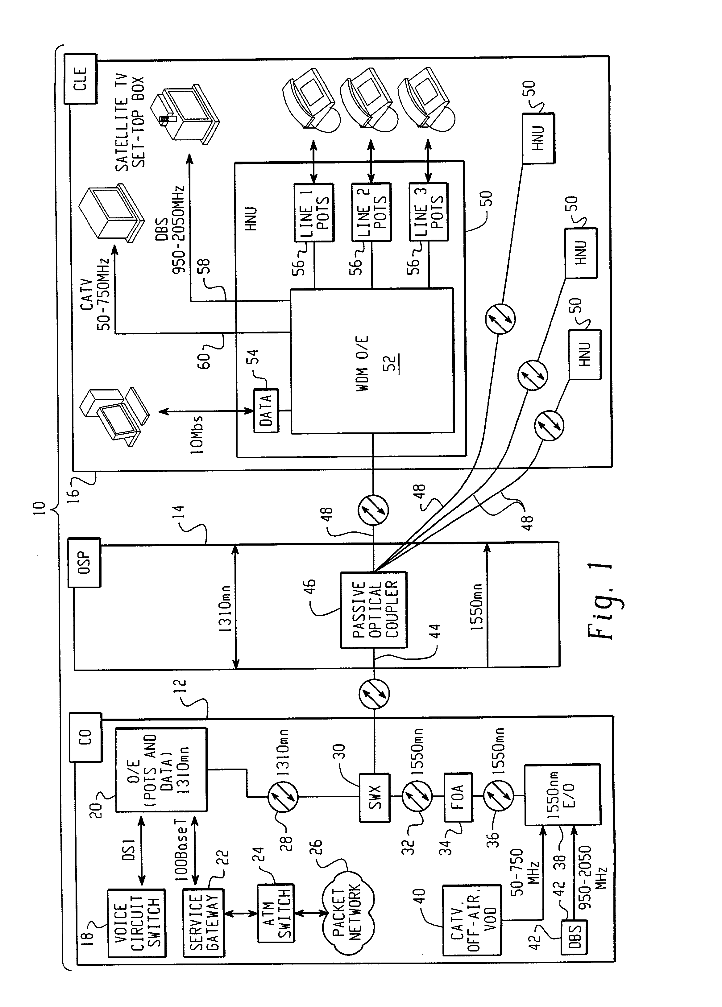
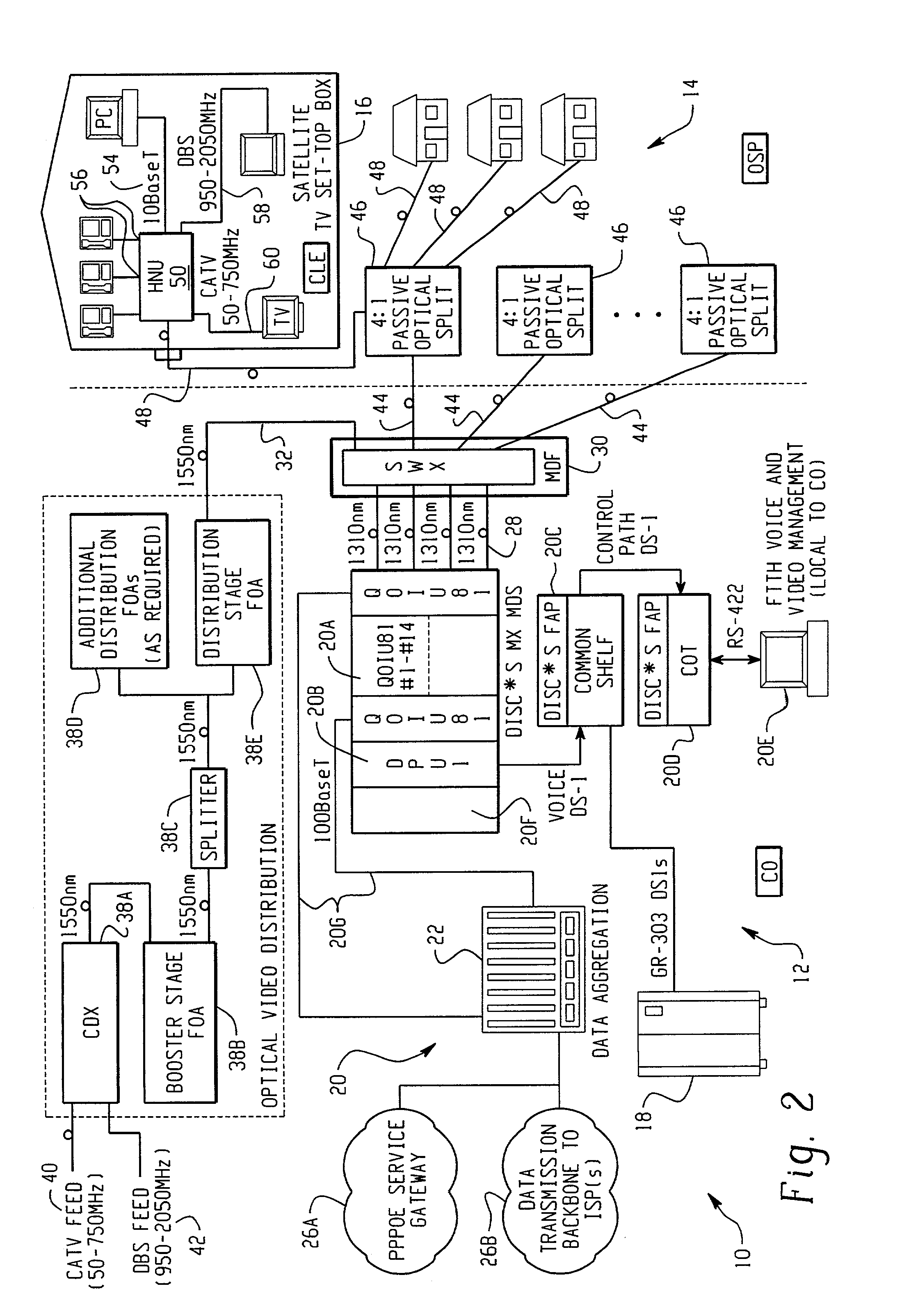
[0144] FIG. 17 sets forth a 1:N reflective passive optical coupler for use in a passive optical network. The use of this unique reflective coupler, in combination with advanced half-duplex signaling techniques, enables the FTTH systems disclosed herein to achieve higher data transmission rates. The 1:N reflective optical coupler 46 is used in place of the 1:4 splitter 46 shown in FIGS. 1-3, and includes a single upstream transmission port coupled to an extension fiber 44, and N downstream transmission ports, which are coupled to a plurality of drop fibers 48.

[0145] With the system shown in FIGS. 1-3, each of the HNUs 50 attached to a particular 1:4 splitter 46 cannot "see" whether the other HNUs 50 are transmitting upstream on the extension fiber 44. Because of this limitation, the system utilized a full-duplex communication protocol in which the central office instructed the HNUs 50 as to when they should communicate upstream on the extension fiber 44. FIG. 7, and accompanying desc...

second embodiment

[0154] FIG. 18 sets forth the reflective passive optical coupler 46 shown in FIG. 17. The structure of the reflective coupler 46 in this embodiment is similar to that shown in FIG. 17, except that it replaces the upstream 1.times.2 splitter / coupler 402 with another 2.times.2 splitter / coupler 404I. This configuration is for use with a system in which the telephony / data signals 28 from the host OIU 20 and the video signals 32 from the video source 40 are delivered over separate extension fibers, and are not combined at the central office SWX equipment 30. In this configuration, the coupler 46 includes two upstream transmission ports, one for each of the extension fibers, and N downstream transmission ports, one for each of the drop fibers.

third embodiment

[0155] FIG. 19 sets forth the reflective passive optical coupler 46 shown in FIG. 17. This embodiment includes a 1.times.2 splitter / coupler 402 coupled to the upstream transmission port, and four additional 1.times.2 splitter / couplers 404E, 404F, 404G, 404H coupled to the eight downstream transmission ports. Coupling the 1.times.2 couplers are three additional 2.times.2 splitter couplers 404A, 404C, 404D.

[0156] FIG. 20 sets forth a timing diagram for communicating over a passive optical network (PON) utilizing one or more of the three reflective optical couplers shown in FIGS. 17-19. The first diagram 410 shows the burst structure on the fiber 44 in which each of the HNUs 50 is enabled for maximum burst length. As shown here, the HNUs 50 transmit in a round-robin order on the fiber 44, starting at HNU N0 through N8 before returning to N0. Preferably, the maximum burst length for each HNU is limited to permit the transmission of time-critical information, and also to ensure that no o...


PUM


Abstract

A Fiber-to-the-Home (FTTH) multi-media access system and method are provided in which voice, video and data signals are transported over a passive optical network (PON) between a central office location and a plurality of subscriber home network units (HNUs). Optical video distribution circuitry and telephony / data distribution circuitry at the central office location are included in the system and operate to send and receive CATV video, PBS video television, telephony and Packet data signals to and from the HNUs via the PON. Optical multiplexing / demultiplexing circuitry operating at the central office combines the video signals, which are operating at one optical wavelength, with the telephony / data signals, which are operating at a second, distinct optical wavelength. These combined optical signals are then transported over the PON to the HNUs. The PON includes a plurality of distribution fibers coupled to a plurality of passive optical splitters, which are each coupled to a plurality of drop fibers that connect to the HNUs. The HNUs receive the combined optical signals, demultiplex and convert the optical signals into corresponding electrical signals, which are in turn coupled through the HNU to the video, data and telephony networks within the home. The HNUs also receive upstream electrical signals from devices within the home, multiplex and convert these electrical signals into upstream optical signals, and transmit these upstream optical signals to the central office.

Description

[0001] This application is a continuation-in-part of U.S. patent application Ser. No. 09 / 537,022, filed on Mar. 28, 2000, and is also related to the following co-pending U.S. patent applications, which farther describe certain elements and aspects of the FTTH Multimedia Access System set forth herein: (1) Ser. No. 09 / 520,587, titled "Splice Tray for use in Splicing Fiber Optic Cables and Housing Therefor," filed on Mar. 8, 2000; (2) Ser. No. 09,532,996 titled "Apparatus for Distributing Optical Fiber Transmission Paths," filed on Mar. 22, 2000; (3) Ser. No. 09 / 540,956, titled "Apparatus and Method for Combining Two Separate RF Signals on a Single Optical Fiber," filed on Mar. 31, 2000; (4) Ser. No. 29 / 120,491, titled "Wall-Mounted Home Network Unit," filed on Mar. 20, 2000; (5) Ser. No. 60 / 186,486, titled "Home Networking Unit," filed on Mar. 2, 2000; (6) Ser. No. 09 / 395,844, titled "Apparatus and Method for Extracting Two Distinct Frequency Bands from Light Received by a Photodiode...

Claims


Application Information

Patent Timeline
Patent Type & Authority Applications(United States)
IPC IPC(8): H04B10/272H04L12/28H04L12/56H04N7/173H04N7/22H04N21/61
CPCH04B10/272H04L12/2801H04L49/201H04L49/351H04N21/6168H04N7/17309H04N7/22H04N21/6118H04L49/357
Inventor KIMBROUGH, MAHLON D.MATTHES, JOHN W.AUTRY, JOHNBUABBUD, GEORGE H.GAINER, JAMES J.ETHRIDGE, BARRY J.
Owner ADVANCED FIBER ACCESS CORP
Why Eureka
Try Eureka