Through-flow type machine set water guiding mechanism

A water guide mechanism, a tubular technology, applied in the field of the water guide mechanism of the tubular unit, can solve the problems of large hydraulic loss, low efficiency, poor water sealing effect, etc., achieve good meshing, improve flow and Excellent energy conversion efficiency and water sealing effect

Inactive Publication Date: 2007-01-03
SICHUAN DONGFENG ELECTRIC MACHINARY WORKS CO LTD
View PDF0 Cites 3 Cited by
  • Summary
  • Abstract
  • Description
  • Claims
  • Application Information

AI Technical Summary

Problems solved by technology

At present, the water guide structure of most tubular turbines has disadvantages such as large hydraulic loss, poor water sealing effect, and low efficiency, which affect the popularization and application of tubular turbines

Method used


Image

  • Through-flow type machine set water guiding mechanism

Examples


Embodiment Construction

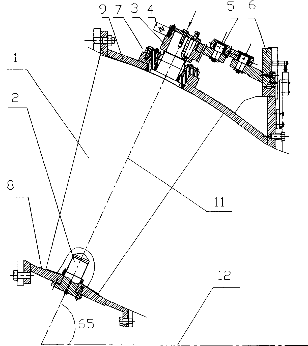
[0011] Such as figure 1 As shown, a water guiding mechanism of a tubular unit includes a guide vane 1, a guide vane lower shaft 2, a guide vane arm 3, a connecting plate 4, a shear pin 5, a control ring 6, a sleeve 7, an inner water distribution ring 8 and The outer water distribution ring 9, the guide vane 1 is conical, the tapered narrow end of the guide vane is connected to the guide vane lower shaft 2, the tapered wide end of the guide vane is passed through the connecting plate 4, the shear pin 5 and the control ring by the guide vane arm 3 in sequence 6 connections. The two ends of the guide vane are of spherical structure, the inner water distribution ring 8 is connected to the tapered narrow end of the guide vane, the sleeve 7 is set on the guide vane arm 3, and the outer water distribution ring 9 is set between the tapered wide end of the guide vane and the sleeve 7, The inner and outer water distribution rings cooperate with the spherical surfaces of the tapered nar...


PUM


Abstract

The present invention discloses a through flow type unit water guide mechanism. It includes the following several portions: guide blade, guide blade lower shaft, guide blade arm, sleeve, connecting plate, shearing pin, control ring and internal and external water distribution rings. Said invention also provides the concrete structure of the above-mentioned every portion, and the working principle of said through flow type unit water guide mechanism.

Description

technical field [0001] The invention relates to a water guiding mechanism of a tubular unit. Background technique [0002] With the development of low-head hydropower stations, tubular turbines have been used more and more widely. At present, the water guide structure of most tubular turbines has disadvantages such as large hydraulic loss, poor water sealing effect, and low efficiency, which affect the popularization and application of tubular turbines. Contents of the invention [0003] The purpose of the present invention is to provide a new type of water guiding mechanism for a tubular unit, which not only ensures that when the water guiding structure is opened, the guide vane can rotate flexibly, has a large flow rate, and has good water guiding performance, but also ensures that when the water guiding structure is closed, the guide vane The meshing surfaces at both ends have good water sealing performance. [0004] The technical solution adopted in the present inven...

Claims


Application Information

Patent Timeline
IPC IPC(8): F03B3/18
CPCY02E10/223Y02E10/20
Inventor 王家玉邓志明李江涛
Owner SICHUAN DONGFENG ELECTRIC MACHINARY WORKS CO LTD
Why Eureka
Try Eureka