Supercharge Your Innovation With Domain-Expert AI Agents!

Vacuum cleaner providing filter-absence detection

一种真空吸尘器、吸尘器的技术,应用在吸尘器、吸滤器、清洁设备等方向,能够解决吸尘器不能工作、阻碍脏物容器封闭、增加制造成本等问题

Inactive Publication Date: 2007-01-10
HOOVER LIMITED
View PDF2 Cites 4 Cited by
  • Summary
  • Abstract
  • Description
  • Claims
  • Application Information

AI Technical Summary

Problems solved by technology

A typical arrangement of this type is disclosed in European patent application EP 1,214,903, where proper installation of the filter causes the spring-loaded tongue to be withdrawn from a position in which the tongue could hinder the closure of the dirt container: no dirt container Properly closed, the vacuum cleaner does not work
This or other mechanical arrangements are often complex and unduly increase manufacturing costs

Method used


Image

  • Vacuum cleaner providing filter-absence detection
  • Vacuum cleaner providing filter-absence detection
  • Vacuum cleaner providing filter-absence detection

Examples


Embodiment Construction

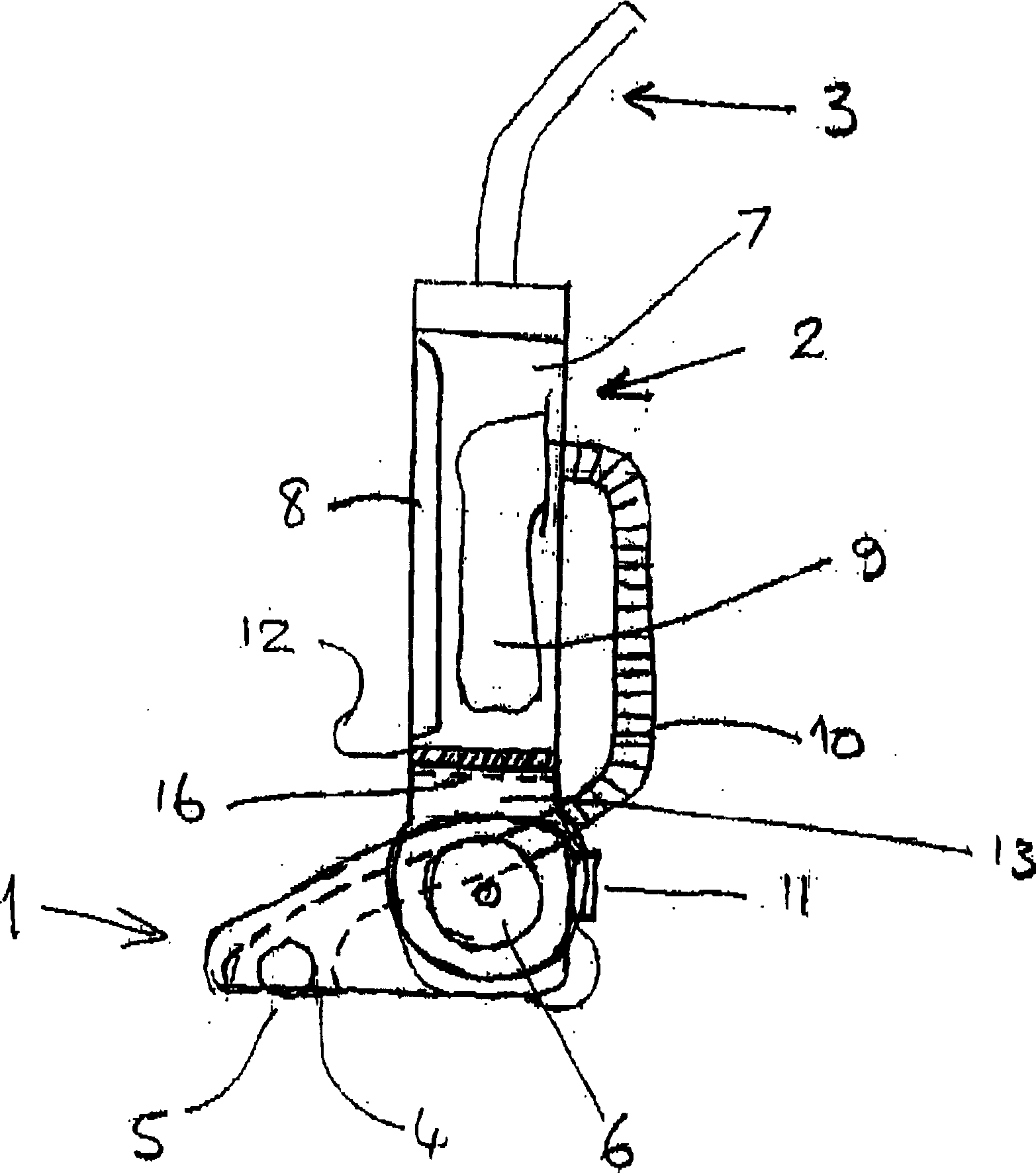
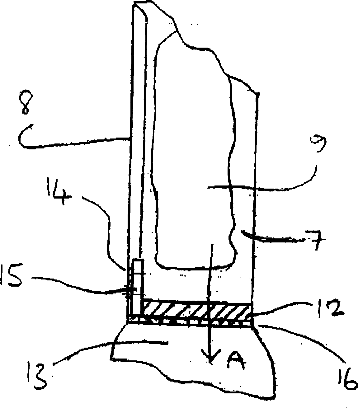
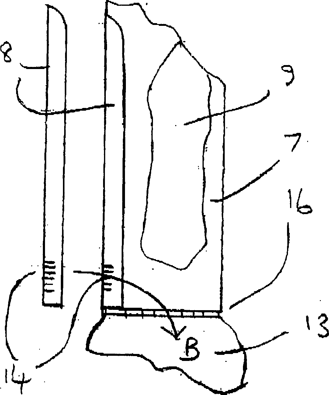
[0020] First refer to the attached figure 1 , shows a conventional upright type vacuum cleaner comprising a grounded foot or base unit 1 to which an upright body 2 is pivotally mounted. The grounding unit 1 is provided on its underside with a suction nozzle or inlet 4 in which a rotating brush 5 is arranged. The upright body 2 comprises a body divided into two chambers, namely a bag chamber 7 which is closed by a removable cover 8 and which in use houses a porous filter bag 9, and a motor chamber 13 which The motor / fan unit 6 is installed in the chamber 13 .

[0021] The motor chamber 13 is divided into two separate areas, one in fluid communication with the bag chamber 7 through the grille 16 and the other in fluid communication with the exhaust outlet 11 . A grid 16 comprising walls or partitions forming a series of openings, in the example shown, effectively forms the floor of the baghouse 7 and supports a filter element 12 arranged in the grid. The upper or upstream sid...


PUM


Abstract

A vacuum cleaner having a filter assembly 12 disposed on grill 16 between the bag chamber 7 and motor chamber 13. Bag chamber 7 has a cover 8. Filter assembly 12 has an upstanding wall 15 provided with a covering of resilient material, e.g. rubber. The cover 8 is formed with a grill 14 in a lower region. When the filter assembly is correctly installed, and the cover 8 is in position, the resilient covering of the upstanding wall 15 rests in sealing contact against the inner surface of the cover 8 and over the grill 14. If the filter assembly 12 is absent, the grill 14 provides direct fluid communication between the bag chamber 7 and the atmosphere. The cleaner will be ineffective in picking up dirt thereby alerting the user to the absence of the filter assembly.

Description

technical field [0001] The present invention relates to a vacuum cleaner and, more particularly, to a vacuum cleaner that enables a user to detect when a filter unit of the vacuum cleaner is absent. Background technique [0002] Modern vacuum cleaners generally operate on the "clean-air fan" principle, according to which the airflow through the vacuum cleaner is generated by a fan located in the airflow at a point downstream of the separator arrangement, so The separator arrangement described above removes dirt and dust from the suction airflow. Dirty air is drawn into the vacuum cleaner through a floor-engaging nozzle or other suction opening and is ducted to a separator arrangement which is connected in fluid communication with the inlet of the fan. The airflow thus passes through the separator arrangement and the fan and is then discharged from the vacuum cleaner to the environment through the outlet opening. The separator arrangement can take any of several forms, with...

Claims


Application Information

Patent Timeline
Patent Type & Authority Applications(China)
IPC IPC(8): A47L9/10A47L9/19A47L9/14
CPCA47L9/122A47L9/1472A47L5/28A47L9/12A47L9/19
Inventor 罗斯·理查森
Owner HOOVER LIMITED
Features
  • R&D
  • Intellectual Property
  • Life Sciences
  • Materials
  • Tech Scout
  • Unparalleled Data Quality
  • Higher Quality Content
  • 60% Fewer Hallucinations
Learn More