Cyclonic separating apparatus for vacuum cleaner which is capable of separately collecting water from dust

a vacuum cleaner and separating apparatus technology, applied in the field of vacuum cleaners, can solve the problems of clogging various filters, paper bags are prone to get wet and rupture, fungus and/or germs are often grown, etc., and achieve the effect of preventing dispersion and subsequent backflow, high separation efficiency of water and minute contaminants, and easy checking of the amount of separated water or contaminants

Inactive Publication Date: 2006-07-27
SAMSUNG GWANGJU ELECTRONICS CO LTD
View PDF4 Cites 165 Cited by
  • Summary
  • Abstract
  • Description
  • Claims
  • Application Information

AI Technical Summary

Benefits of technology

[0008] It is a second object of the present invention to provide a cyclonic separating apparatus which provides high separation efficiency of both water and minute contaminants.
[0009] It is a third object of the present invention to provide a cyclonic separating apparatus which is capable of preventing dispersion and subsequent backflow of both water and minute contaminants once separated.
[0010] It is a fourth object of the present invention to provide a cyclonic separating apparatus in which the amount of separated water or contaminants can be easily checked.
[0014] At least one guide member may be further provided to partition the second chamber of the dust receptacle so as to restrict rotation, dispersion, and subsequent backflow of the water once the water is separated into the second chamber.

Problems solved by technology

The problem is fungus and / or germs frequently grow due to the presence of water with the collected contaminants.
Additionally, when a paper bag is employed in the dust separating apparatus, the paper bag is prone to get wet and rupture.
In the case of a cyclone dust separating apparatus, separated water may flow backward with the discharging air current, clogging various filters such as an exhaust filter.
Accordingly, due to the light weight of the separated minute contaminants, these contaminants may flow backward with the discharging air current, clogging various filters such as an exhaust filter.

Method used


Image

  • Cyclonic separating apparatus for vacuum cleaner which is capable of separately collecting water from dust
  • Cyclonic separating apparatus for vacuum cleaner which is capable of separately collecting water from dust
  • Cyclonic separating apparatus for vacuum cleaner which is capable of separately collecting water from dust

Examples


Embodiment Construction

[0025] Certain embodiments of the present invention will now be described in greater detail with reference to the accompanying drawings.

[0026] In the following description, the same drawing reference numerals are used for the same elements throughout the drawings. Also, well-known functions or constructions are not described in detail since they would obscure the invention in unnecessary detail.

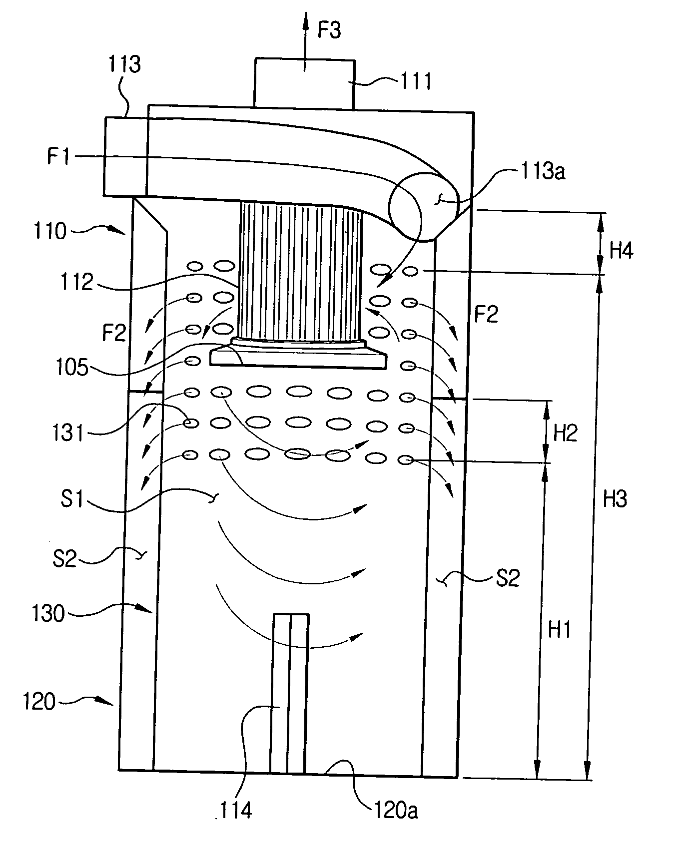
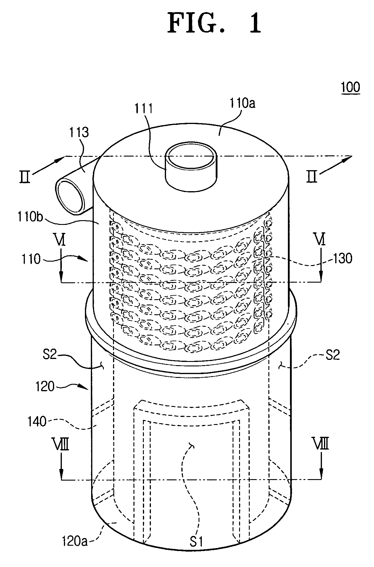
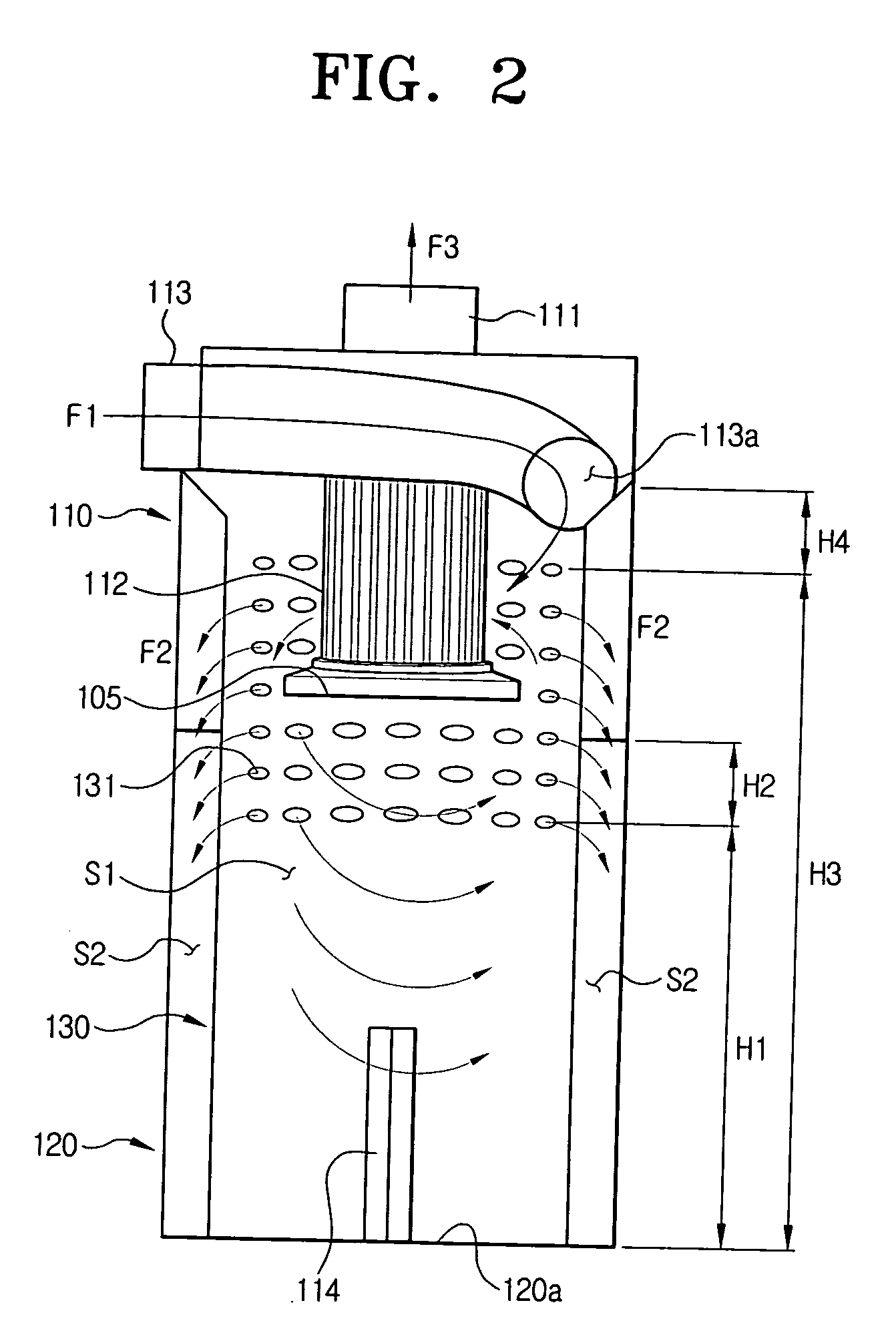
[0027] Referring to FIG. 1, a cyclonic separating apparatus 100 according to an embodiment of the present invention includes a cyclone body 110, a dust receptacle 120, a screen 130 and a guide member 140.

[0028] The cyclone body 110 takes on the configuration of a cylindrical container in which dust and water are separated from the drawn air by centrifugal force. The cyclone body 110 includes an air discharge passage 111 on its upper side 110a through which clean air, free of water and dust, is discharged. The air discharge passage 111 may take on the configuration of a cylindrical pipe, wh...


PUM

PropertyMeasurementUnit
distances H2aaaaaaaaaa
angleaaaaaaaaaa
elliptical shapeaaaaaaaaaa

Abstract

A cyclonic separating apparatus for a vacuum cleaner that can separately collect dust and water. The cyclonic separating apparatus includes: a cyclone body having an air inlet passage and an air discharge passage; a dust receptacle connected to a lower end of the cyclone body; and a screen dividing the cyclone body and interior space of the dust receptacle into a first chamber and a second chamber, the screen having a plurality of passing holes, wherein drawn air rotates in the first chamber and water separated from the air moves to the second chamber through the passing holes.

Description

CROSS-REFERENCE TO RELATED APPLICATIONS [0001] This application claims the benefit of Korean Patent Application No. 2005-06524 and 2005-32835 filed Jan. 25, 2005 and Apr. 20, 2005, respectively, in the Korean Intellectual Property Office. The entire contents of each of the above mentioned applications is incorporated herein by reference. BACKGROUND OF THE INVENTION [0002] 1. Field of the Invention [0003] The present invention relates to a vacuum cleaner. More particularly, the present invention relates to a cyclonic separating apparatus for a vacuum cleaner, which is capable of separately collecting water and dust from air. [0004] 2. Description of the Related Art [0005] Generally, a cyclonic separating apparatus of a vacuum cleaner collects contaminants from a place being cleaned, and the collected contaminants usually include both water and dust. The problem is fungus and / or germs frequently grow due to the presence of water with the collected contaminants. Additionally, when a pa...

Claims


Application Information

Patent Timeline
Patent Type & Authority Applications(United States)
IPC IPC(8): B01D50/00
CPCA47L7/0004A47L7/0038A47L7/0042A47L9/1683B04C5/10B04C5/185
Inventor OH, JANG-KEUNKIM, MIN-HA
Owner SAMSUNG GWANGJU ELECTRONICS CO LTD
Why Eureka
Try Eureka