Towing arrangement and deformation tube in a railway vehicle coupling

A technology of traction device and deformation tube, which is applied in the direction of traction device, vehicle parts, traction connector, etc., and can solve the problems of long coupler length, difficult structure, high manufacturing cost, etc.

Active Publication Date: 2007-02-14
DELLNER COUPLERS AB
View PDF1 Cites 21 Cited by
  • Summary
  • Abstract
  • Description
  • Claims
  • Application Information

AI Technical Summary

Problems solved by technology

But the main disadvantage of this solution is that the crash protection is length-based, that is, the entire coupler is required t

Method used


Image

  • Towing arrangement and deformation tube in a railway vehicle coupling
  • Towing arrangement and deformation tube in a railway vehicle coupling
  • Towing arrangement and deformation tube in a railway vehicle coupling

Examples


Embodiment Construction

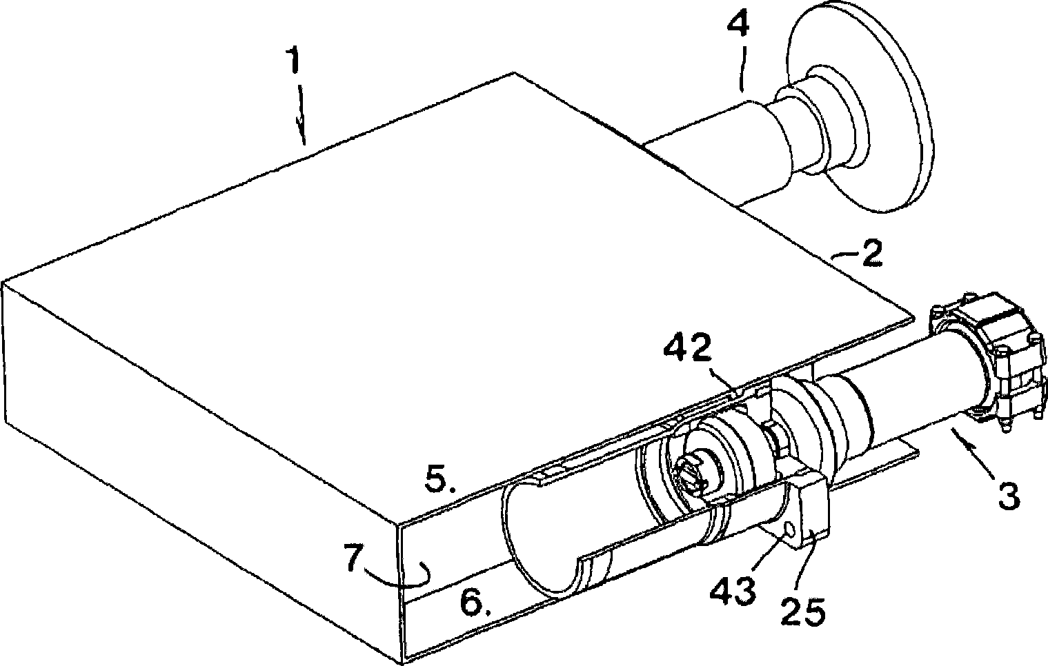
[0015] exist figure 1 In , 1 is generally used to denote a frame included in any vehicle unit (for example, a car, locomotive or similar device), which together with other vehicle units may form an EMU. For those of ordinary skill in the art, a vehicle frame sometimes also means a vehicle body or a chassis. One end 2 of the vehicle frame is equipped with a traction device represented by 3 as a whole, and two dead blocks 4, figure 1 Only one is shown in . In the illustrated vehicle frame there are two plates or panels 5, 6 forming a hollow space 7 between them. In this hollow space, the rear part of the traction device 3 is accommodated, while the front part of the traction device protrudes a distance from the end 2 of the vehicle frame. In this regard, it should be clear that the terms "front" and "rear" respectively refer to the traction device and not to the frame. In other words, in the term chosen, it does not matter whether one end 2 of the car is facing forward or ba...


PUM


Abstract

The invention relates to a towing arrangement being intended for train couplers and of the type that comprises a bar (8), which at a rear end has an axially projecting pin (10), which projects through a through hole (40) in a plate (11), which on botte sides is surrounded by shock-absorbing spring members (12), which always aim to hold the pin in a starting position in relation to the plate, and against the action of which the pin together with the bar are axially movable. According to the invention, the plate (11) is included in a mandrel (16) equipped with a cone (19), which mandrel is inserted into a deformation tube (17), more precisely into a wide, front tube section (22), which via a waist (23) transforms into a thinner, rear tube section (21), which is deformable by the mandrel (16). In a particular aspect, the invention also relates to a deformation tube as such.

Description

technical field [0001] In a first aspect, the present invention relates to a pulling device for a railway coupler, said device comprising a rod at its rear end comprising an axially protruding pin protruding through a through hole in a plate, the two plates The sides are surrounded by shock-absorbing elastic elements which always serve to keep the pin in its starting position relative to the plate and resist the movement of the pin and the rod moving axially together. Background technique [0002] Although the actual purpose of devices of the above type is to provide not only traction but also propulsion between different wheel support units in a train unit, for example between cars and / or locomotives. Those of ordinary skill in the art generally refer to this as a "pulling device". These towing devices are characterized in that the towing device comprises a rod or positioning arm (usually in the shape of a tube) the rear end of which is fixed in one way or another to one e...

Claims


Application Information

Patent Timeline
IPC IPC(8): B61G5/02B61G9/04B60D1/50B61G9/06B61G9/22
CPCB60D1/50B61G9/22B61G9/06
Inventor M·霍格布林
Owner DELLNER COUPLERS AB
Why Eureka
Try Eureka