
Drain connection and drain pipe using same

A technology for drainage pipes and drainage branch pipes, which is applied in the directions of pipes/pipe joints/pipe fittings, drainage structures, adjustable connections, etc. Ease of work and improved workability

Inactive Publication Date: 2007-04-04
KUBOTA CI CO LTD
View PDF1 Cites 5 Cited by
  • Summary
  • Abstract
  • Description
  • Claims
  • Application Information

AI Technical Summary

Problems solved by technology

[0005] However, in the drain pipe joint of Patent Document 1, since the branch pipe connecting portion connecting each of the branch drain pipes is provided only on the side of the joint main body, it may be difficult to drain the water when there is an obstacle on the side of the drain pipe joint, for example. Connection of branch pipe to drain pipe joint
[0006] In the drain pipe joint of Patent Document 1 described below, since the connection between each branch drain pipe and the branch pipe connection part can only be performed in a state where the axes of the two are aligned, there is a fear of inconvenience in piping construction.
[0007] In addition, in the drain pipe joint of the above-mentioned Patent Document 1, since the cross-sectional height dimension of the joint main body is much larger than that of the above-mentioned drain main pipe, it may be difficult to perform the drain pipe joint especially in a low-floor house with a narrow underfloor space. set up

Method used


Image

  • Drain connection and drain pipe using same
  • Drain connection and drain pipe using same
  • Drain connection and drain pipe using same

Examples


Embodiment Construction

[0038] Preferred embodiments of the present invention will be described with reference to the drawings.

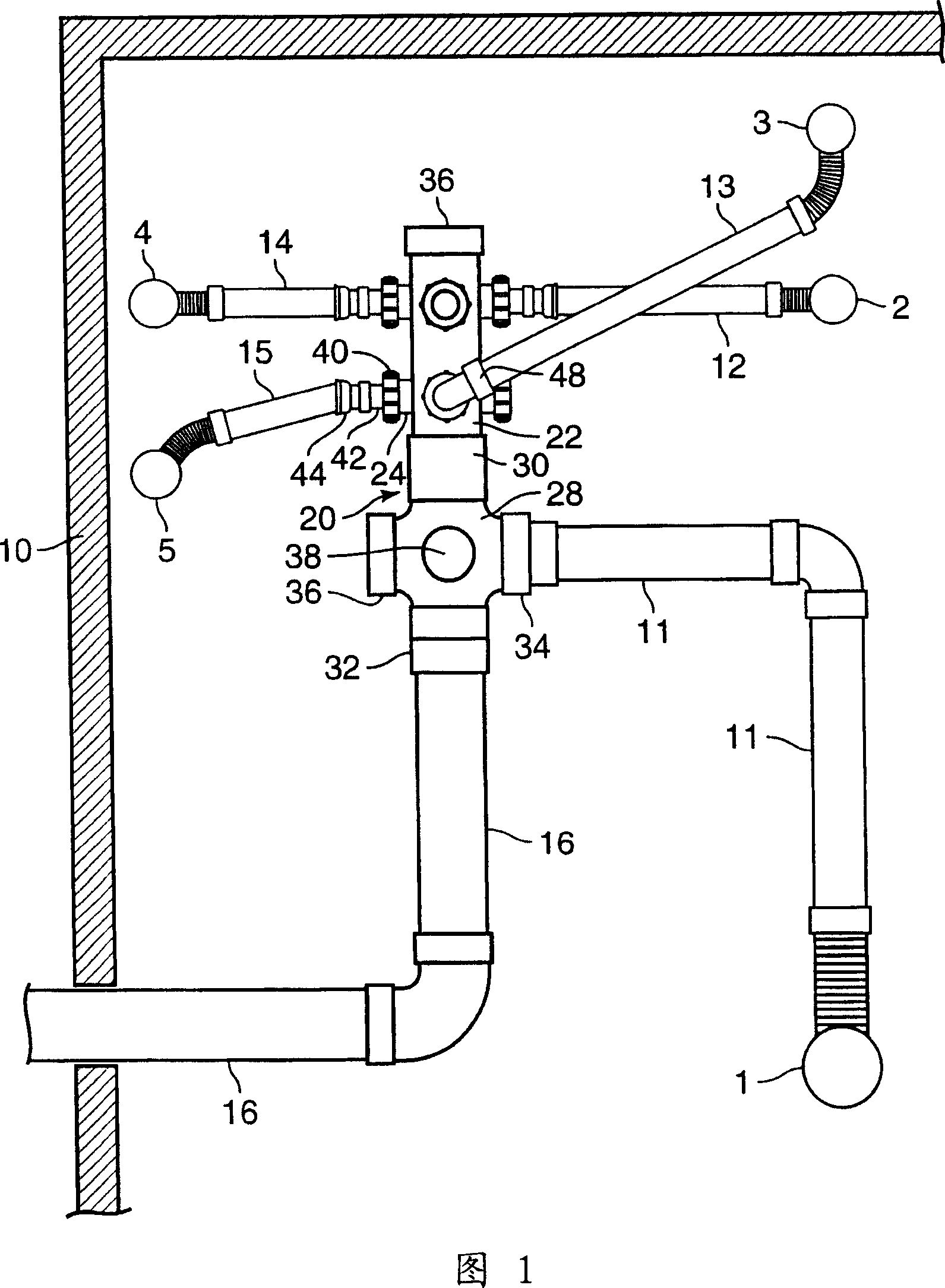
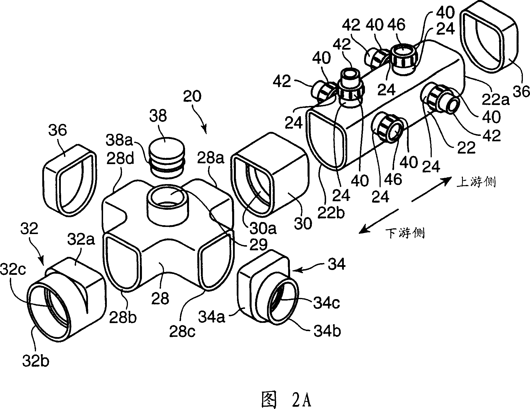
[0039] FIG. 1 is a diagram of a drain piping facility using a drain joint 20 of the present embodiment. As shown in this figure, the drain pipe joint 20 is provided in the inner area of ​​the outer peripheral foundation 10 that is compacted under the floor of a building such as a house. The drainage pipe joints 20 are respectively connected to the drainage branch pipes extending from the drainage equipment (first lowered to the floor and then extended in the horizontal direction) composed of the toilet 1, the bathroom 2, the washing machine 3, the kitchen 4, and the washbasin 5 installed in the building. 11-15, through these branch drain pipes 11-15, the drainage generated by the above-mentioned drainage devices is collected to the drain pipe joint 20. And, on the downstream side (lower side in FIG. 1 ) of this drain pipe joint 20, a drain main pipe 16 is connected. omit...


PUM


Abstract

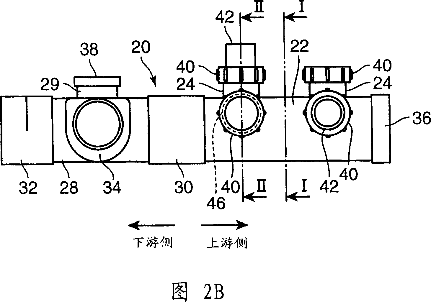
The present invention relates to a drain pipe joint capable of improving the workability of the drain piping equipment, and a drain pipe structure using the same. The drain pipe joint 20 functions to conjoin drainage discharged from drain branch pipes 11 to 15 extending from a plurality of drain fittings 1 to 5, respectively, and to discharge the drainage to a downstream drain main pipe 16. The drain pipe joint 20 has a cylindrical joint main body 22, one end of which is provided with discharging opening communicated with a drain main pipe 16, and has a plurality of branch pipe connection portions 24, which may be connected to each of the drain branch pipe 12 to 15, formed in a peripheral wall thereof. The side surface and the upper surface of the joint main body 22 are provided with one or more branch pipe connection portions 24 respectively.

Description

technical field [0001] The present invention relates to a drainage pipe joint for converging the drainage inflowing from various drainage branch pipes extending from a plurality of drainage facilities such as houses (such as toilets and bath rooms) to flow out to a main drainage main pipe on the downstream side, and a drainage pipe structure using the same . Background technique [0002] As the above-mentioned drain pipe joint, for example, a configuration described in Patent Document 1 below is known. The drain pipe joint (drain bucket) described in this patent document 1 is constituted by: a cylindrical joint main body (bucket main body) which has a larger cross-section than the main drain main pipe located on the downstream side of the joint (in particular, the dimensional ratio in the height direction of the cross-section). The size of the drain main pipe is large); the branch pipe connection part (branch inlet), which is a part protruding from the side of the above-men...

Claims


Application Information

Patent Timeline
Patent Type & Authority Applications(China)
IPC IPC(8): E03C1/12
CPCE03C1/1222E03F5/105F16L27/04
Inventor 石川浩大霜新三郎四元友治今久保谦一郎
Owner KUBOTA CI CO LTD
Learn More