Container lid of operation type vacuum valve

A technology for sealing containers and vacuum valves, which is applied in the direction of containers, caps, and seals. It can solve the problems that the mold cannot be separated, the ring groove is impossible, and the traditional technology cannot actually adapt to industrial production.

Inactive Publication Date: 2007-05-23
HANA COBI PLASTIC
View PDF0 Cites 16 Cited by
  • Summary
  • Abstract
  • Description
  • Claims
  • Application Information

AI Technical Summary

Problems solved by technology

However, in the above-mentioned conventional art, it is impossible to form an annular groove opening in the horizontal direction for the reason described later.
That is, since the downwardly curved peripheral portion 31 is formed on the outer peripheral portion of the container cap 21 and surrounds the outer peripheral portion 24a of the container body 24, and the downwardly curved peripheral portion 31 and the annular groove 30 simultaneously achieve ideal Design conditions, so manufacturing by injection molding is still not possible, i.e., in the above construction, the mold cannot be separated during manufacturing
Therefore, the conventional technology shown in Fig. 4 cannot be practically adapted to industrial production

Method used


Image

  • Container lid of operation type vacuum valve
  • Container lid of operation type vacuum valve
  • Container lid of operation type vacuum valve

Examples


Embodiment Construction

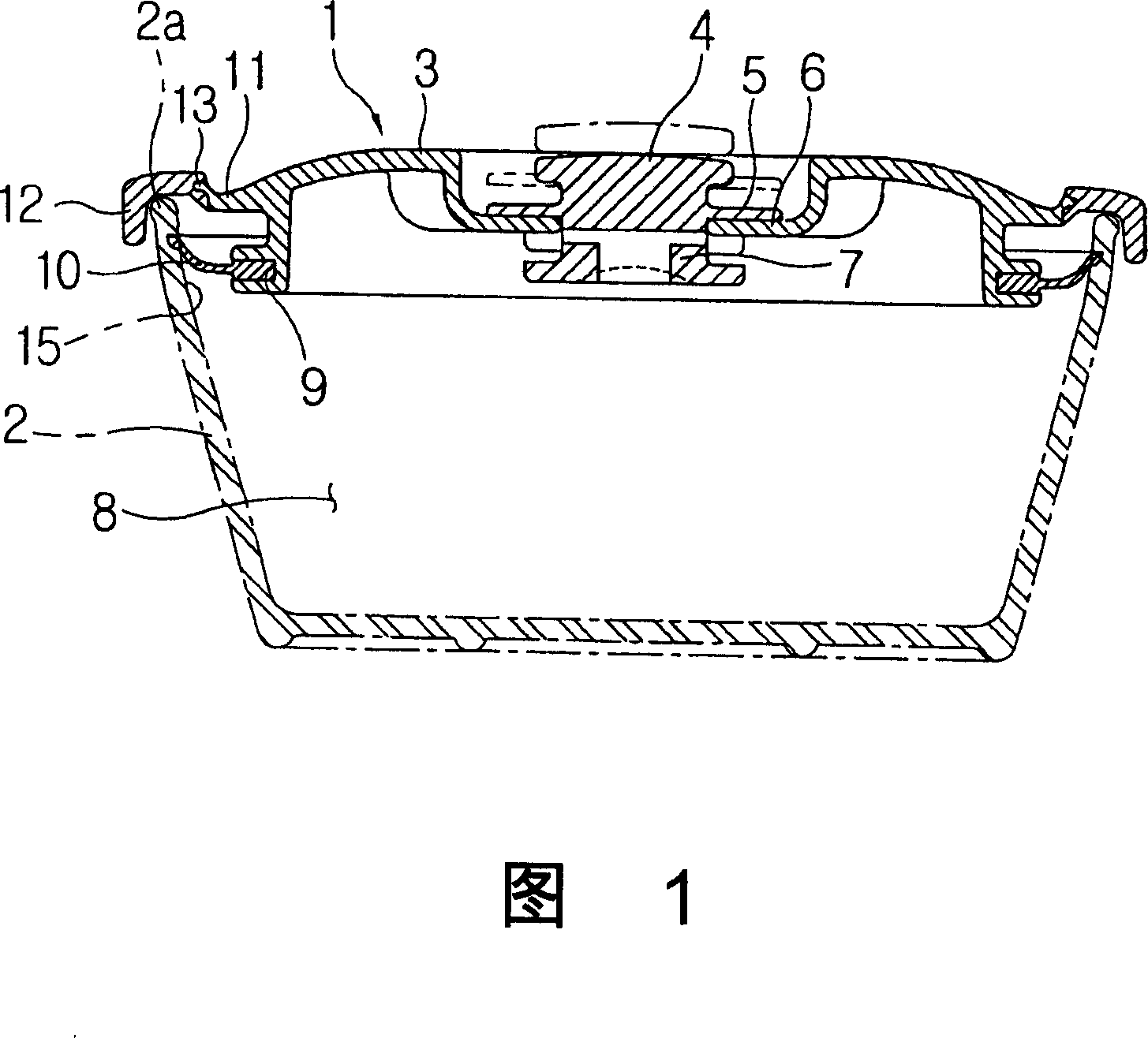
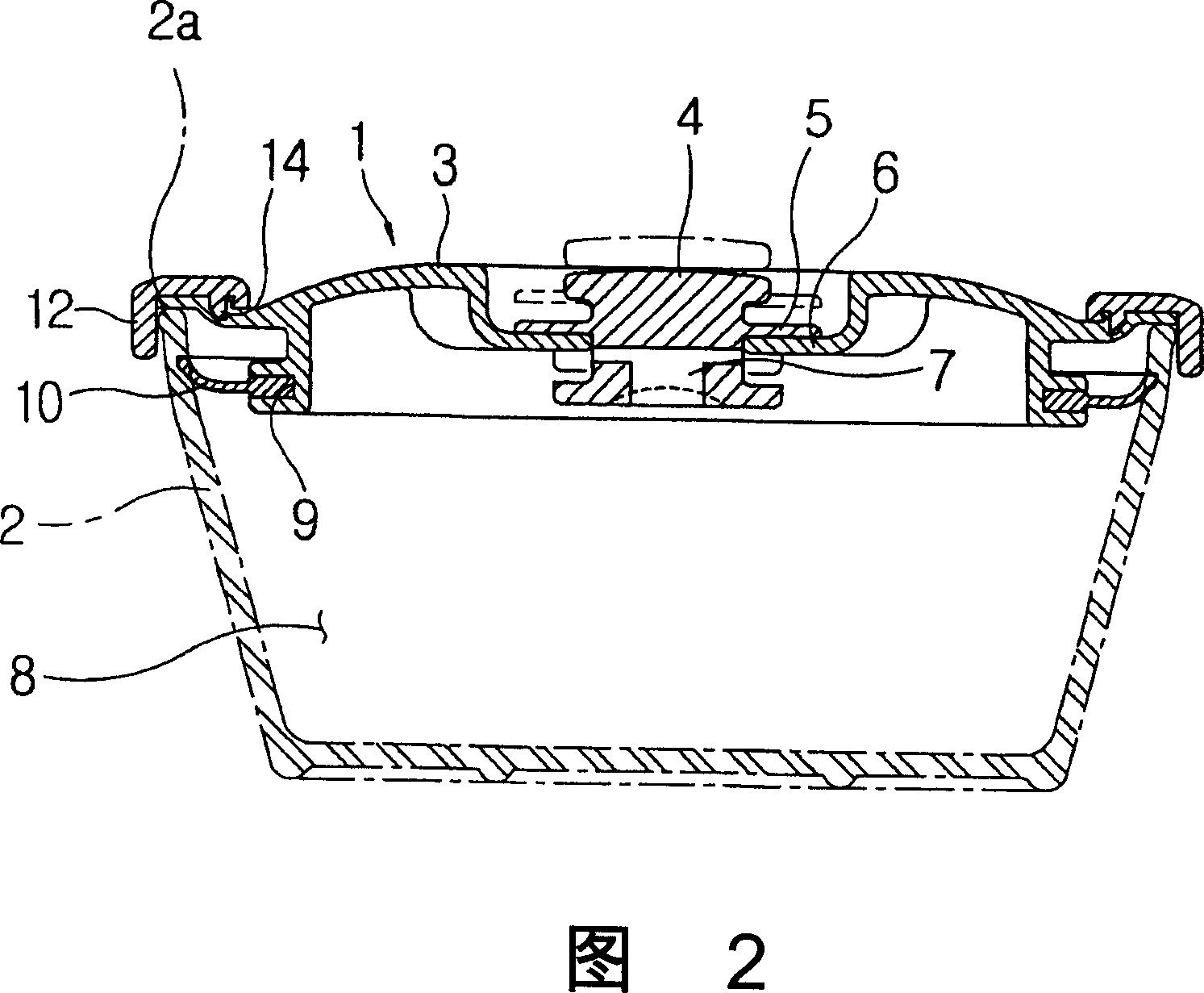
[0015] Fig. 1 is a view showing a sealed container lid with an operating vacuum valve according to the present invention, and Fig. 2 is a view showing a belt of a double injection molding structure according to a specific example embodiment of the present invention. Double-injection structure of the airtight container lid of the operation type vacuum valve.

[0016] In the figure, reference numeral 1 denotes a container cap, and 2 denotes a container body, where the container cap 1 is opened or closed.

[0017] A vacuum valve 4 for opening or closing the lid is installed on the lid body 3 of the container lid 2 . When the valve seat 5 of a vacuum valve 4 is lifted off the valve seat 6, the inside 8 of the container body 2 is opened to the outside through the valve hole 7. When it is pressed against the valve seat 6, the valve hole 7 is closed, and the inside 8 of the container body 2 is not communicated with the outside.

[0018] An annular groove 9 is formed on the cover bo...


PUM


Abstract

A sealed container lid of a vacuum valve operation type is provided, in which an engagement structure of a silicon packing is simple, and a relatively strong sealing force is obtained. A process for engaging or disengaging a lid to a container body may be performed based one-touch method. The sealed contained lid of a vacuum valve operation type comprises a body which is injection-molded and has a circular groove formed in a horizontally and outwardly opened shape for an engagement of the silicon packing, and a downwardly bent peripheral part which is formed at an outer peripheral part of the body based on a double injection method while surrounding the same.

Description

field of invention [0001] The present invention relates to a sealed container lid with a vacuum valve. Background technique [0002] Usually, airtight container all adds a cover outside to cover container when sealing storage certain raw material, and sealing pad is contained in the container lid, and sealing pad keeps the edge of container body in close contact. Sealed containers may be provided with locking wings to allow the lid to achieve a sealing engagement. [0003] However, in a cap joining method with a simple structure, there is a disadvantage of insufficient sealing strength. In an example with the locking wing method, although the sealing strength of the cover will be better, it is inconvenient to open or close the locking wing during use. [0004] As shown in FIG. 3, a vacuum valve 22 is installed at the center of the container lid 21. As shown in FIG. A silicon gasket 23 is mounted adjacent to the outside of the container body. When the container cover 21 i...

Claims


Application Information

Patent Timeline
Patent Type & Authority Applications(China)
IPC IPC(8): B65D81/20B65D51/16B65D53/00B65D43/02
CPCB65D2543/00537B65D2543/00361B65D2543/00796B65D51/1683B65D2543/00685B65D2543/00759B65D2543/00555B65D2543/0024B65D2543/00629B65D2543/00092B65D2543/0062B65D43/0218B65D81/2038B65D2543/00518B65D31/14B65D47/24B65D53/02B65D81/20
Inventor 金昶浩
Owner HANA COBI PLASTIC
Why Eureka
Try Eureka