Inner circle machining method and internal grinder therefor

A processing method and technology of internal grinding machines, which are applied in the direction of grinding machines, machine tools designed for grinding the rotating surface of workpieces, metal processing equipment, etc., can solve the problems of high cost, difficulty in meeting the manufacturing accuracy requirements of sleeve-type spindle units, and difficulties in realization, etc. question

Inactive Publication Date: 2007-06-06
钟洪
View PDF0 Cites 10 Cited by
  • Summary
  • Abstract
  • Description
  • Claims
  • Application Information

AI Technical Summary

Problems solved by technology

Such a standard is difficult to achieve, and even if it can be achieved, the cost is very high
The existing internal grinding machine f

Method used


Image

  • Inner circle machining method and internal grinder therefor
  • Inner circle machining method and internal grinder therefor
  • Inner circle machining method and internal grinder therefor

Examples


Example Embodiment

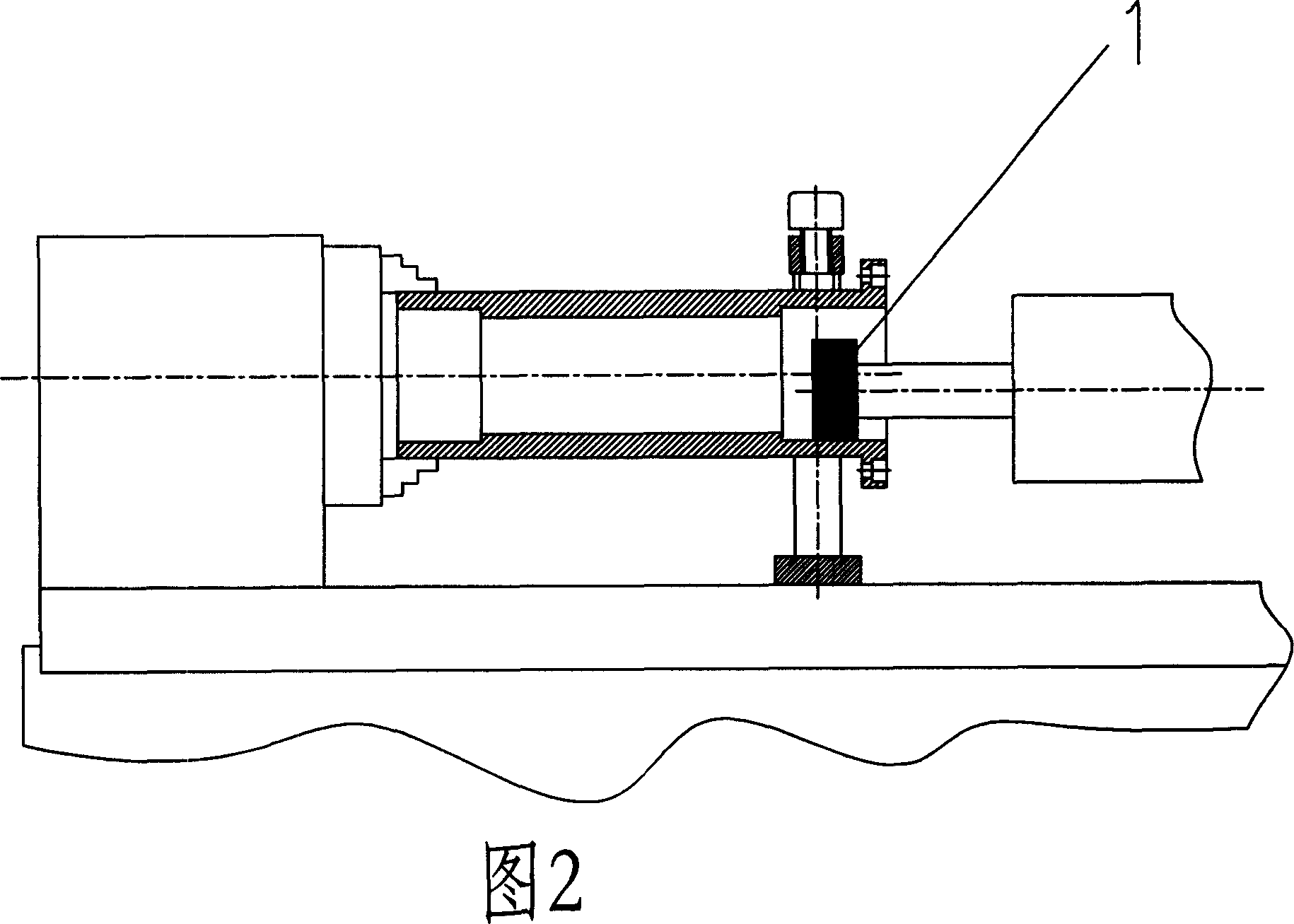
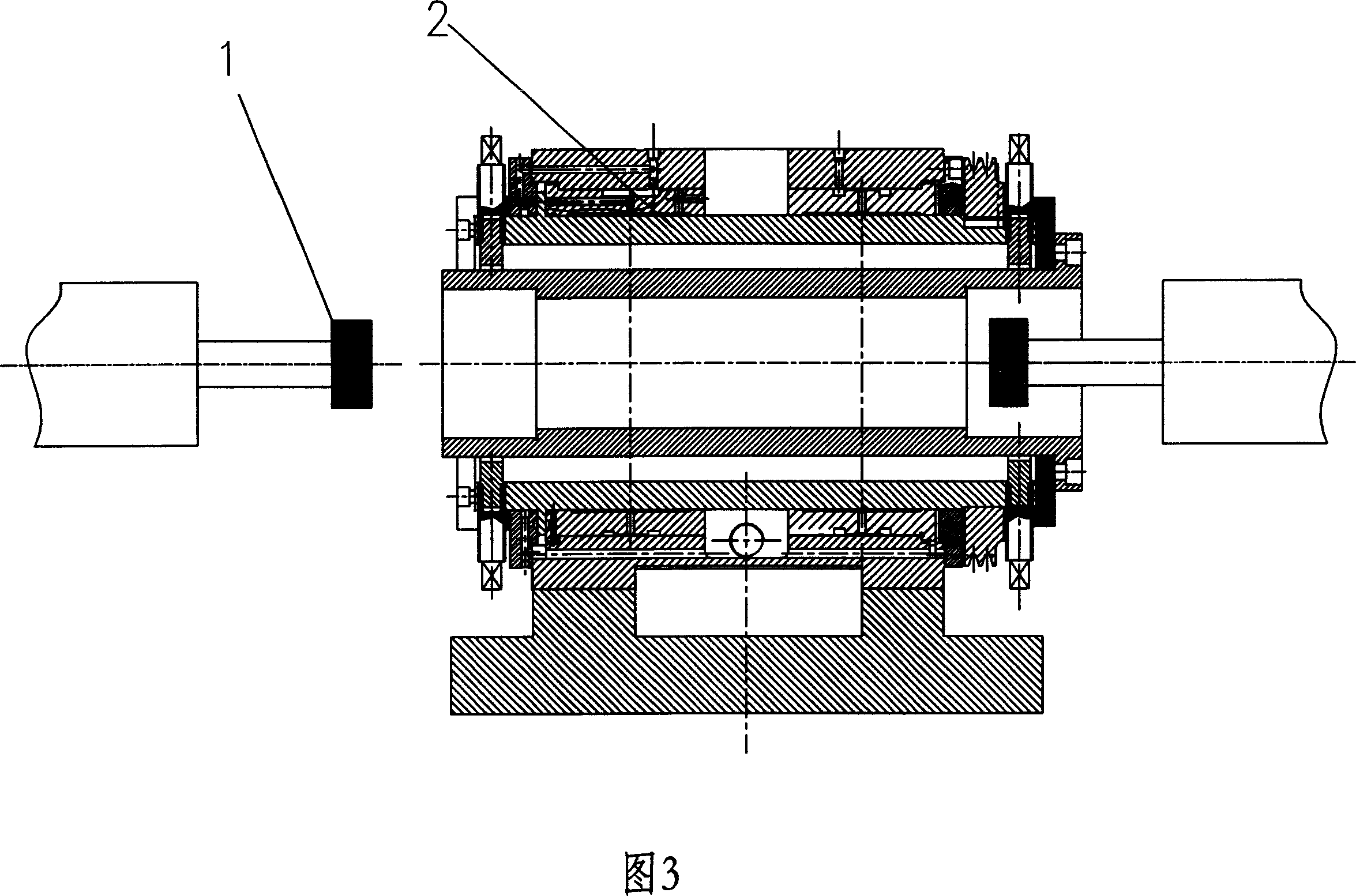
[0022] As shown in FIG. 3 , the present invention includes two grinding heads 1 oppositely arranged, and a headstock hollow main shaft 2 capable of clamping workpieces is arranged between the two grinding heads.

[0023] The headstock hollow spindle 2 gives priority to the static pressure spindle with high rotary precision. The hydrostatic spindle with high rotary precision is an existing technology, and its rotary precision can reach below 0.003mm.

[0024] The internal grinding machine of the present invention can be horizontal (as shown in Figure 4), vertical (as shown in Figure 5) or refitted from existing grinding machines (as shown in Figure 6).

[0025] The headstock hollow main shaft 2 can also choose a rolling bearing main shaft or a sliding bearing main shaft, which can also achieve the purpose of the present invention.

[0026] The present invention processes the inner circle of the workpiece according to the following steps:

[0027] A. Clamp the workpiece on the...


PUM


Abstract

The present invention discloses one kind of inner circle machining method and the internal grinder therefor. The present invention has the typical application of machining high precision sleeve type spindle unit. By means of setting two grinding head spindle units separately on two sides of the headstock spindle unit to clamp the workpiece, the two sides of the workpiece may be machined after once clamping and this can raise the coaxiality of the machined end holes of the sleeve.

Description

Technical field: [0001] The invention relates to an inner circle processing method and an inner circle grinding machine using the method, and its typical application occasion is for machining a sleeve of a high-precision sleeve type spindle unit. Background technique: [0002] The typical design of the sleeve-type spindle unit is shown in Figure 1. There is a high-precision inner hole at both ends of the sleeve of the high-precision sleeve-type spindle unit. In order to ensure the reliability of the transmission, the coaxiality of the two inner holes is very demanding. High, usually below 0.01mm. Grinding is an important processing method for high-precision spindle sleeves. As shown in Figure 2, since the traditional grinding machine has only one grinding head, the spindle unit must be clamped on the head frame, the spindle unit rotates, the grinding head enters the tool, and the inner hole at one end is processed first, after the cutting is completed, the grinding head ret...

Claims


Application Information

Patent Timeline
IPC IPC(8): B24B5/40
CPCB24B5/40B24B5/10
Inventor 钟洪
Owner 钟洪
Why Eureka
Try Eureka