Preform conveyor system provided with means for ejecting badly seized

A conveying system, technology for preforms, applied in the direction of conveyors, conveyor items, transport and packaging, etc.

Inactive Publication Date: 2007-06-13
SIDEL PARTICIPATIONS SAS
View PDF1 Cites 7 Cited by
  • Summary
  • Abstract
  • Description
  • Claims
  • Application Information

AI Technical Summary

Problems solved by technology

[0015] [15] Such devices, although satisfactory, have their limitations, especially when the conveying system has to run at high speed, so that some preforms cannot be properly caught by the gripping device, which will lead to major failures of the machine

Method used


Image

  • Preform conveyor system provided with means for ejecting badly seized
  • Preform conveyor system provided with means for ejecting badly seized
  • Preform conveyor system provided with means for ejecting badly seized

Examples


Embodiment Construction

[0035] [35] Hereinafter, the same, similar or analogous elements will be assigned the same reference numerals.

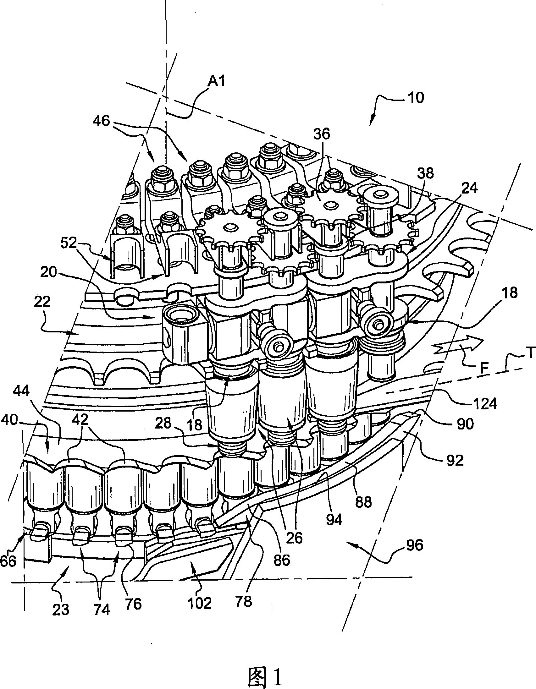
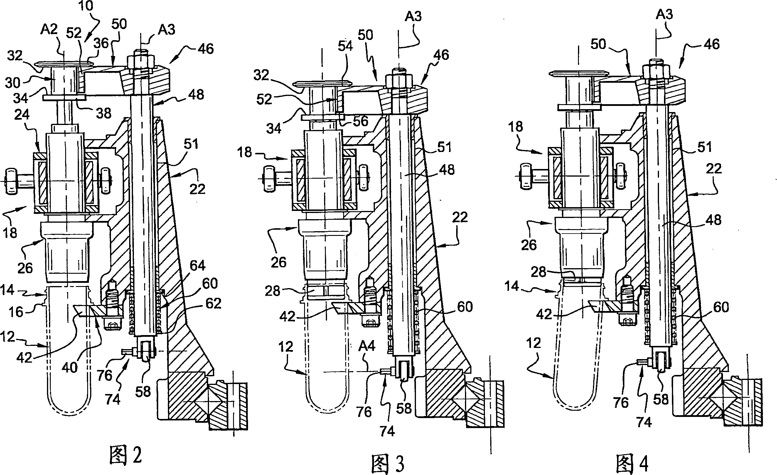
[0036] [36] FIGS. 1 to 4 show a delivery system 10 of a plant for manufacturing containers of thermoplastic material by blow molding from preforms 12 obtained beforehand by injection moulding.

[0037] [37] Each preform 12 is in tubular form, closed at one end and having at its other end the defined shape of a container neck 14 obtained by preworking, defined towards the top by an external annular coupling 16 its boundaries.

[0038] [38] The conveying system 10 comprises a plurality of conveying elements 18 interconnected so as to form an endless chain 20 and designed to convey the preforms 12 in the downstream direction indicated by the arrow F in FIG. 1 .

[0039] [39] Only a portion of the chain 20 is shown in FIG. 1 . This part of the chain 20 comprises in this example two conveying elements 18 .

[0040] [40] The chain 20 part of the conveying element 18 is...


PUM


Abstract

The invention relates to a preform conveyor system (10) comprising a set of transporting elements (18) each of which is provided with at least one grasping device (26) which carries a preform and is movable between a top release position and a lower grasping position. Said invention is characterised in that each grasping device (26) in connected in the axial upward and downward displacement to an associated bracket (46), said bracket (46) comprises a clamp (74) slidingly interacting with a fixed ramp (78) when the grasping device (26) is in the intermediate axial position between the top release position and the lower grasping position thereof in such a way that the axial sliding of the grasping device (26) is generated towards the top release position thereof.

Description

technical field [0001] [01] The present invention relates to a preform delivery system. [0002] [02] The invention relates in particular to a conveying system for the installation of containers of thermoplastic material produced by blow molding from preforms, a conveying system of this type comprising a plurality of conveying elements each having At least one gripping device for carrying the preforms, so as to transport the preforms in a vertical position along the downstream direction of the path inside the apparatus, each gripping device in this type of conveying system can be relative to the carrying Its conveying element moves along a vertical axis so that it engages axially in the neck of the preform to be gripped when it is brought from the upper release position to the lower gripping position. Background technique [0003] [03] Such delivery systems can be found in container blow molding machines, in which the preform obtained beforehand by injection molding is inse...

Claims


Application Information

Patent Timeline
Patent Type & Authority Applications(China)
IPC IPC(8): B29C49/42B65G17/32B65G47/84B65G47/86
CPCB65G17/323B29C49/06B29C49/4205B65G47/842B65G2201/0247B29C49/42085B29C2949/0715
Inventor C·杜德蒙
Owner SIDEL PARTICIPATIONS SAS
Why Eureka
Try Eureka