
Bearing-holder support for rotating elements

A technology for rotating components and bearing seats, which is applied in the direction of rotating bearings, rigid supports of bearing components, bearings, etc., which can solve the problems of difficult manufacturing and cost saving

Active Publication Date: 2007-06-20
AB SKF
View PDF2 Cites 8 Cited by
  • Summary
  • Abstract
  • Description
  • Claims
  • Application Information

AI Technical Summary

Problems solved by technology

[0010] Although the bearing seat support described in European Patent No. 0219115 overcomes the technical problems of the bearing seat support described in European Patent No. 0043429, it is still not easy to manufacture and does not save costs, and it also includes other disadvantages, such as The mounting of the chock support to the washing machine requires blocking both bearings, although European Patent No. 0219115 also describes a third mold for making the cartridge and housing 15 for co-molding with the chock support

Method used


Image

  • Bearing-holder support for rotating elements
  • Bearing-holder support for rotating elements
  • Bearing-holder support for rotating elements

Examples


Embodiment Construction

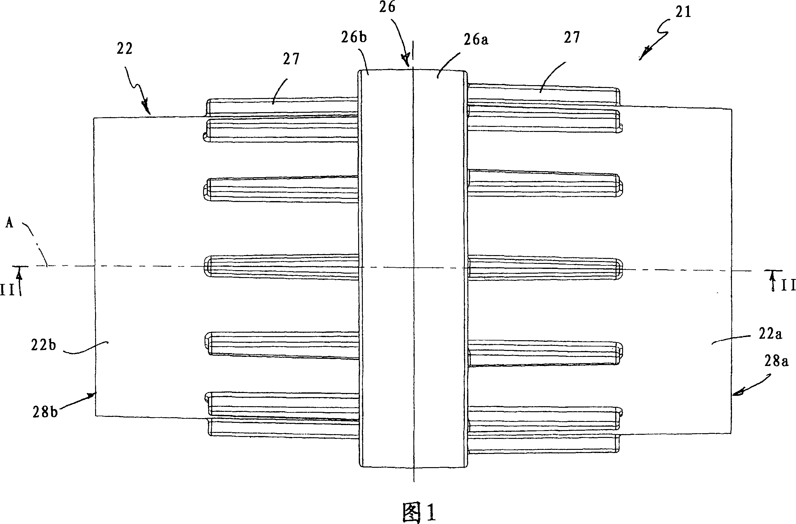
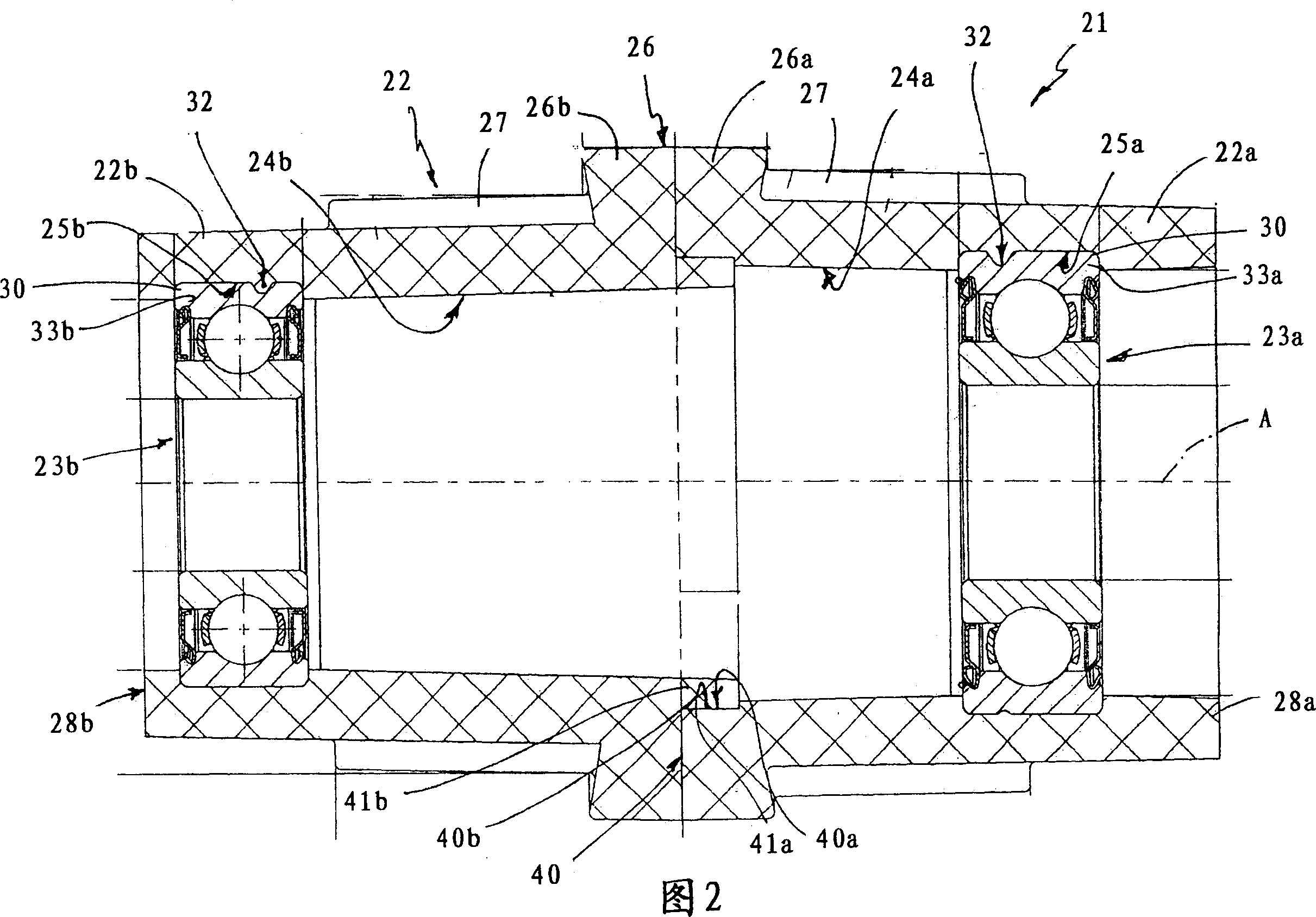
[0019] With reference to Figures 1 and 2, the same or similar parts as described hereinbefore up to the content of this specification are designated by the same reference numerals, the number 21 designating the whole of the bearing housing support for the rotating element, which is represented by the previous Delimited by a tub 7 of a loading washing machine 5 , the front-loading washing machine comprises a tub 6 , a tub 7 and a motor shaft 11 for actuating the tub 7 itself.

[0020] The cylinder 6 is made of plastic material and has, on the side opposite said loading side, a tubular casing 15 extending along the axis A, in which the bearing block support 21 is adapted to be housed so that The motor shaft 11 cooperates therethrough and allows the rotation of the cartridge 7, which is arranged suspended on the shaft 11 itself.

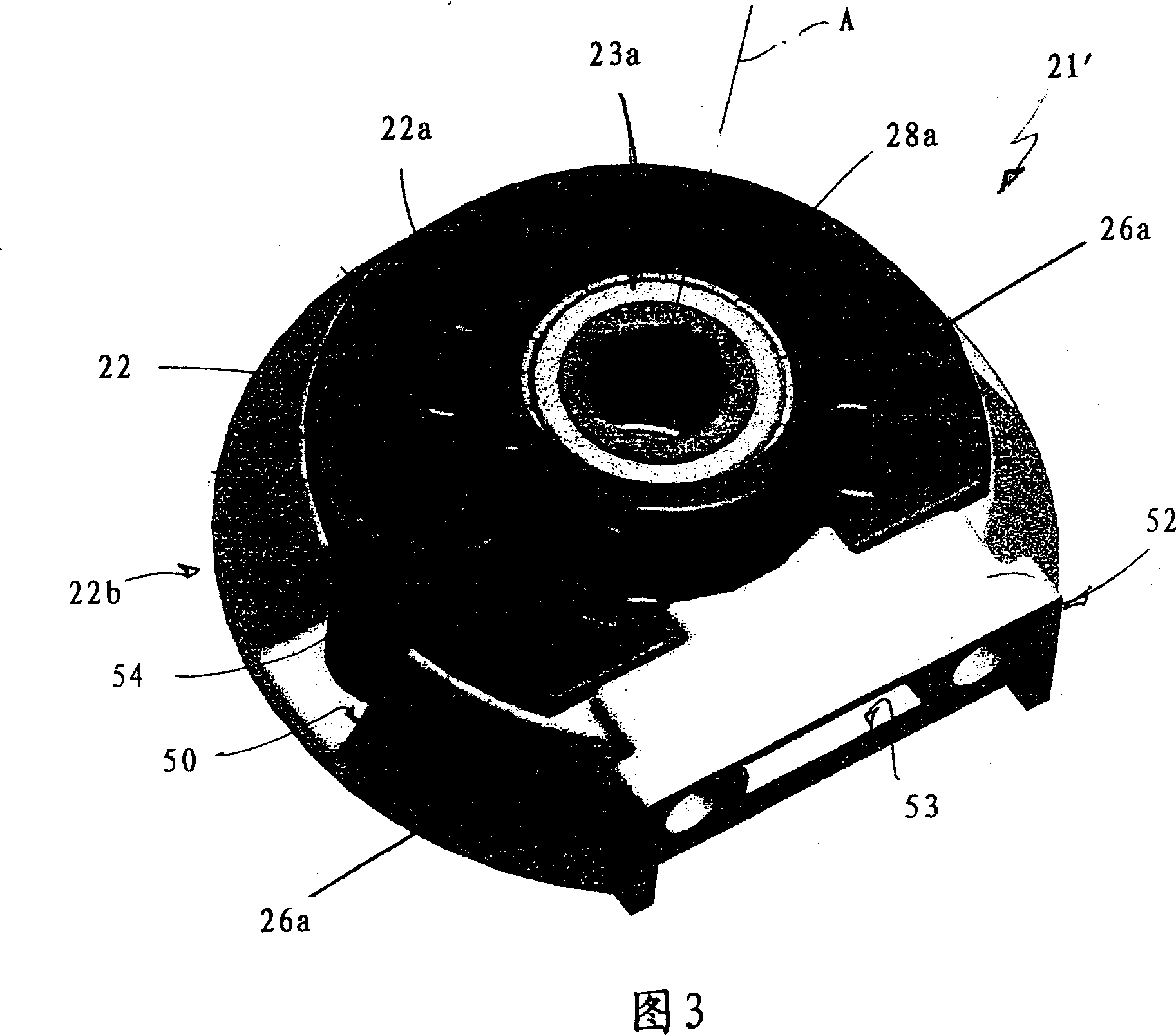
[0021] The support 21 comprises a tube 22 made of plastic material and two rolling contact bearings 23a, 23b, preferably arranged in the tube 22 itself...


PUM


Abstract

Bearing-holder support (21) for rotating elements, the bearing-holder support (21) being suitable forbeing engaged by a shaft (11), and being provided with two rolling contact bearings (23a) (23b), and atubular plastic tube (22) which extends along a longitudinal axis A of the motor shaft and presents two inner annular housings (25a)(25b) for housing the two bearings (23a) (23b); the plastic tube (22) being made up of two modular semitubes (22a) (22b), each of which presents a relative annular housing (25a) (25b) which is obtained by co-moulding of the modular portion itself with a relative bearing (23a) (23b) in order to axially block the bearing (23a) (23b) itself inside the annular housing (25a) (25b) itself.

Description

technical field [0001] The invention relates to bearing housing supports for rotating elements. [0002] The invention can be advantageously applied in the field of bearing housing supports for rotating elements, such as washing machines or more particularly washing machine drums, or textile machines or more particularly spindles of textile machines. Background technique [0003] The following description will refer to washing machines as an example, but can also be transferred mutatis mutandis to the field of textile machines. [0004] As shown in the attached drawing entitled "Prior Art", a known type of bearing housing support for washing machines has a longitudinal axis A and is interposed between the motor shaft 11 of the cylinder 6 and drum 7 to allow the motor shaft 11 and the barrel 7 itself rotates relative to the cylinder 6 . In the more specific case of a front-loading washing machine, or more specifically where the tub 7 is supported in a hanging fashion, the c...

Claims


Application Information

Patent Timeline
Patent Type & Authority Applications(China)
IPC IPC(8): F16C35/00D06F39/00D01H13/00D03D49/00
CPCD06F37/22F16C35/067F16C35/04B29C45/1459F16C2340/00F16C35/042F16C19/56
Inventor R·莫拉G·斯卡尔特里蒂F·加卢奇
Owner AB SKF
Learn More