Ice-making device and refrigerator using the same

A technology for refrigerators and ice-making trays, applied in the fields of refrigerators and ice-making devices, can solve the problems of scattered parts, wrong assembly, disengagement of trays 81 and 83, etc.

Active Publication Date: 2007-07-04
PANASONIC CORP
View PDF1 Cites 31 Cited by
  • Summary
  • Abstract
  • Description
  • Claims
  • Application Information

AI Technical Summary

Problems solved by technology

[0007] However, in the above configuration, in the state where the unit 85 is removed from the frame 83

Method used


Image

  • Ice-making device and refrigerator using the same
  • Ice-making device and refrigerator using the same
  • Ice-making device and refrigerator using the same

Examples


Embodiment Construction

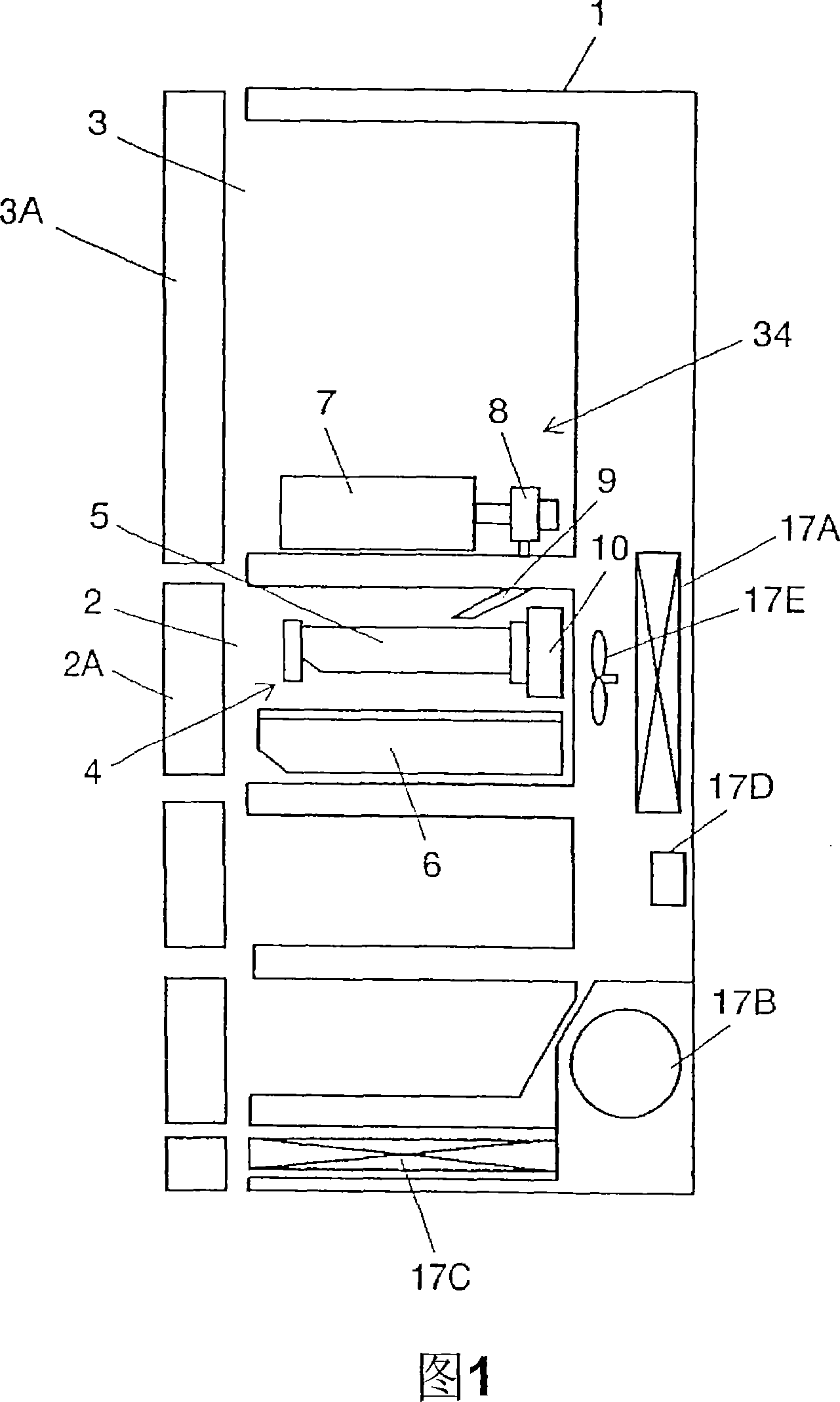
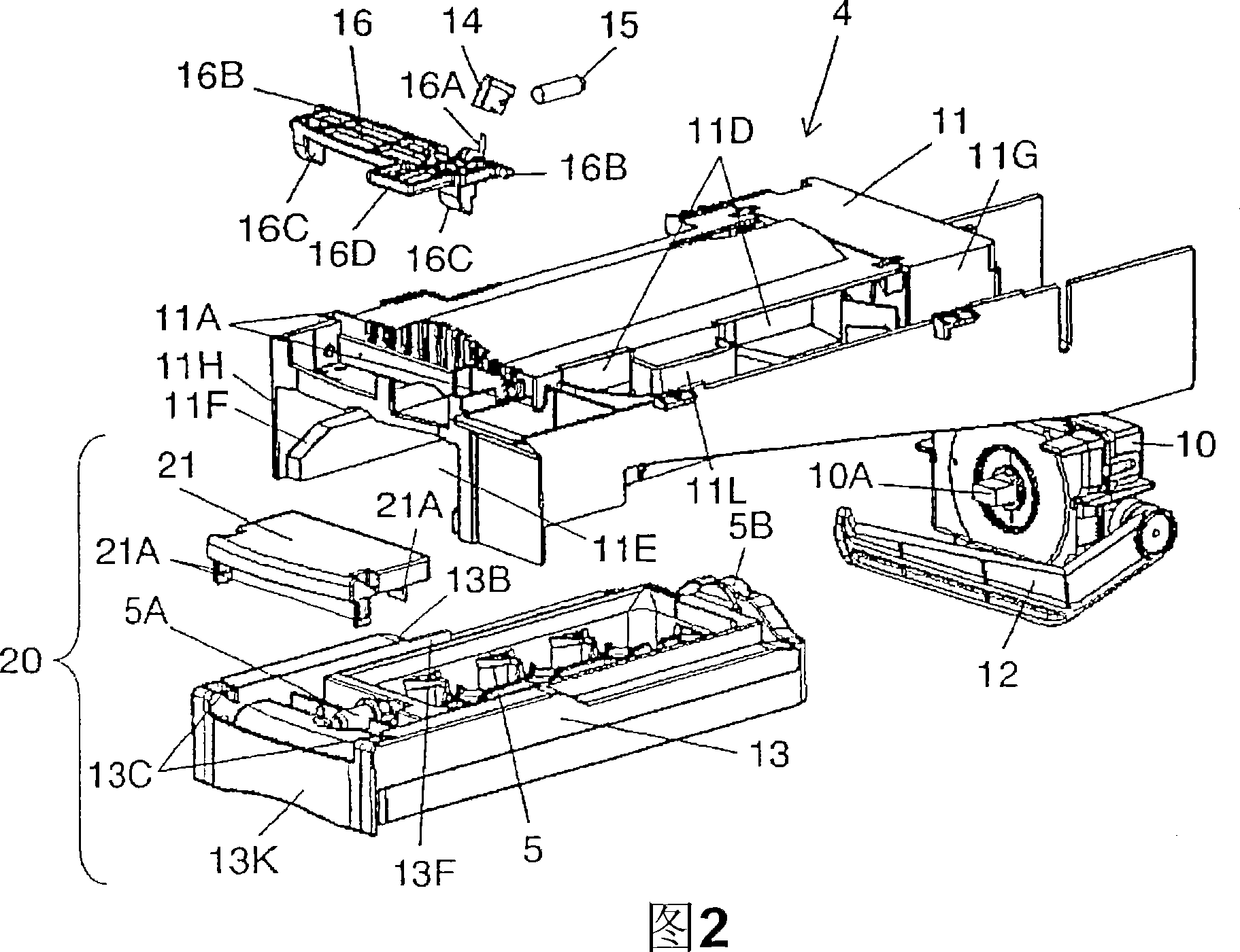
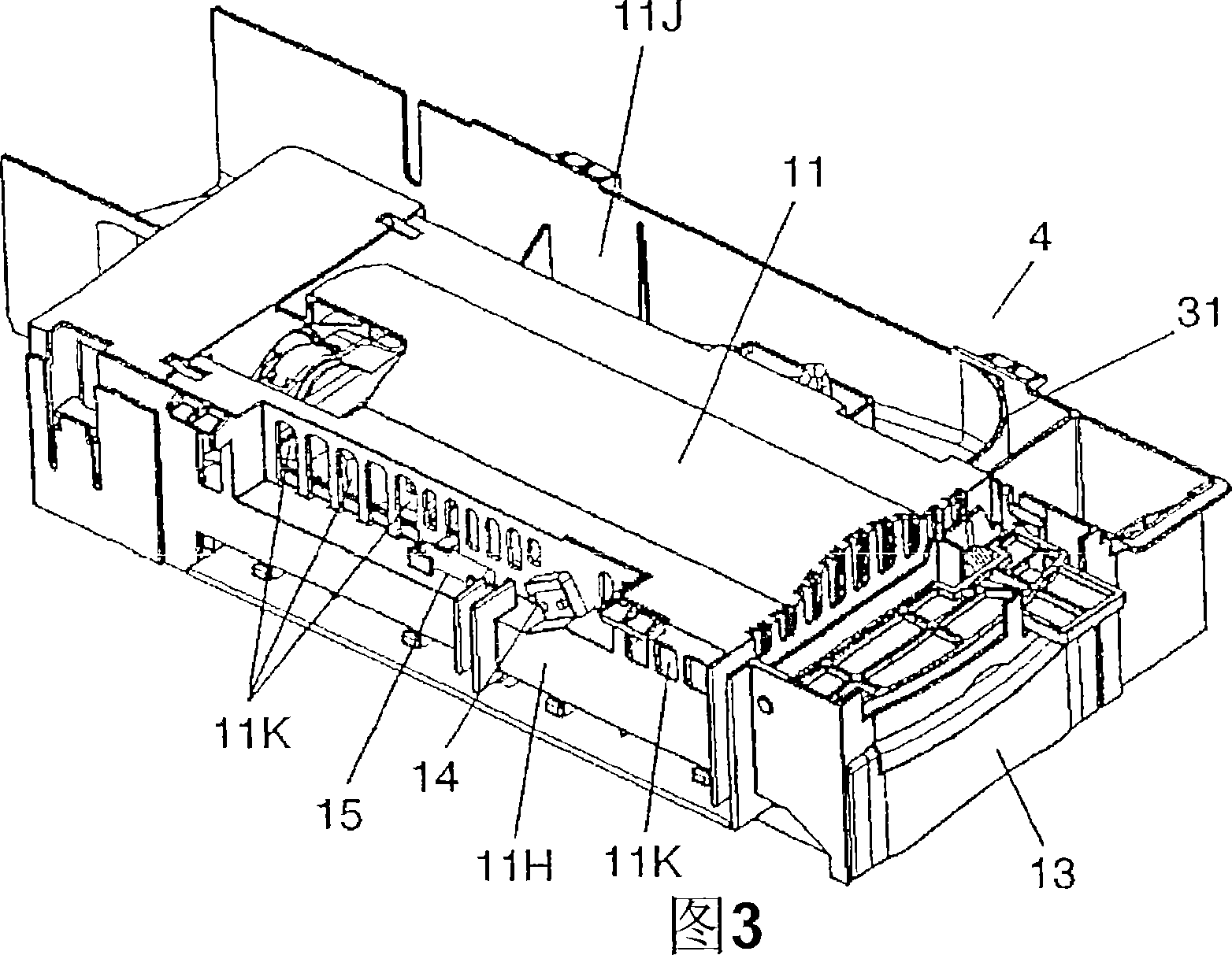
[0031] Fig. 1 is a schematic side sectional view of the refrigerator in the embodiment of the present invention. Fig. 2 is an exploded perspective view of the ice making device in the same embodiment. Fig. 3 is a perspective view of the ice making device shown in Fig. 2 . Fig. 4 is an exploded perspective view of an ice tray unit in the ice maker. Fig. 5 is a cross-sectional view of the refrigerator shown in Fig. 1, showing the top of the ice making device shown in Fig. 3 . Fig. 6 is an A-A cross-sectional view of the same ice-making device as shown in Fig. 5, Fig. 7 is a schematic diagram of the state where the ice-making tray unit is pulled out in Fig. 6, Fig. 8 is a B-B of the same ice-making device shown in Fig. 5 Sectional view. 9A and 9B are diagrams showing the operating state of the micro switch. Fig. 10 is a side sectional view for explaining another structure of the ice making device. 11 is an enlarged view of key parts showing another ice tray holding structure...


PUM


Abstract

An ice-making device installed in an ice-making chamber with a door, comprising an ice-making pan, a drive part, a holding body, and a holding part. The ice-making pan further comprises a first shaft part installed in the direction of the door and a second shaft part installed in the direction opposite to the door, and water to be frozen is supplied thereinto. The drive part further comprises a rotating shaft detachably connected to the second shaft part of the ice-making pan, and is installed at a position opposite to the door of the ice-making chamber. The drive part separates an ice from the ice-making pan by providing a force to the ice when the ice is generated by the freezing of the supplied water. The holding body supports the first shaft part and the second shaft part of the ice-making pan, and is formed integrally with the ice-making pan to form an ice-making pan unit. The holding part supports at least either of the first shaft part and the second shaft part by holding in association with the holding body.

Description

technical field [0001] The present invention relates to an ice making device and a refrigerator provided with the ice making device. Background technique [0002] For example, Japanese Unexamined Patent Publication No. 2001-116410 discloses a conventional refrigerator having an ice maker and a detachable ice tray unit. [0003] FIG. 18 is an exploded perspective view of the automatic ice making device of the refrigerator, and FIG. 19 is an exploded perspective view of an ice tray unit in the automatic ice making device shown in FIG. 18 . [0004] The automatic ice making device includes: an ice making tray (hereinafter referred to as a tray) 81 , an ice removing mechanism 82 , a frame 83 and a loading and unloading mechanism 84 . The deicing mechanism 82 is used to separate the ice made from the tray 81 from the tray 81 . The frame 83 is used to accommodate appliances such as the tray 81 and the deicing mechanism 82 . In order to detachably hold the disk 81 , a detachable...

Claims


Application Information

Patent Timeline
IPC IPC(8): F25C1/10
Inventor 上野孝治高西英知足立正江坂拓南川崎龙也兵藤明
Owner PANASONIC CORP
Why Eureka
Try Eureka