Discharge occurrence status evaluation device and evaluation method

a technology of discharge occurrence and status, which is applied in the direction of dielectric strength testing, optic methods, instruments, etc., can solve the problems of inability to consider a technique for suppressing discharge, inability to know the timing of use of this discharge detection function, and inability to measure electrostatic discharge at present. to achieve the effect of promotion

Inactive Publication Date: 2018-07-03
NAT UNIV CORP KYUSHU INST OF TECH (JP)
View PDF3 Cites 2 Cited by
  • Summary
  • Abstract
  • Description
  • Claims
  • Application Information

AI Technical Summary

Benefits of technology

[0014]According to the present invention, it is possible to know the timing (occurrence time after voltage application) at which dielectric breakdown occurred and the dielectric breakdown voltage in an electrostatic test performed through use of an electrostatic discharge tester. As a result, it becomes possible to know not only the presence / absence of occurrence of dielectric breakdown, which has been conventionally estimated, but also the state of occurrence of discharge and the breakdown voltage. As a result, when the waveform of the applied voltage is known, the discharge voltage can be defined (there is a definition in which when dielectric breakdown occurs at the wave front, its instantaneous value is the voltage at which discharge occurs, and when dielectric breakdown occurs at the wave tail, its peak value is the voltage at which discharge occurs).
[0015]When this voltage can be known, it becomes possible to promote the studies of discharge physics for understanding the discharge phenomenon occurring when a voltage having a steep waveform is applied as in the case of electrostatic discharge ESD, and it becomes possible to more specifically grasp the discharge occurrence status in product development and product inspection.

Problems solved by technology

However, mere use of this discharge detection function does not allow us to know the timing at which discharge occurred and the instantaneous voltage at the time of occurrence of discharge.
Therefore, information sufficient to consider a technique for suppressing discharge has not been obtained.
Since a probe, such as a potential divider, which allows an oscilloscope to measure such a steep high voltage waveform is not available on the market, there is a problem in that electrostatic discharge cannot be measured at present.

Method used


Image

  • Discharge occurrence status evaluation device and evaluation method
  • Discharge occurrence status evaluation device and evaluation method
  • Discharge occurrence status evaluation device and evaluation method

Examples


Embodiment Construction

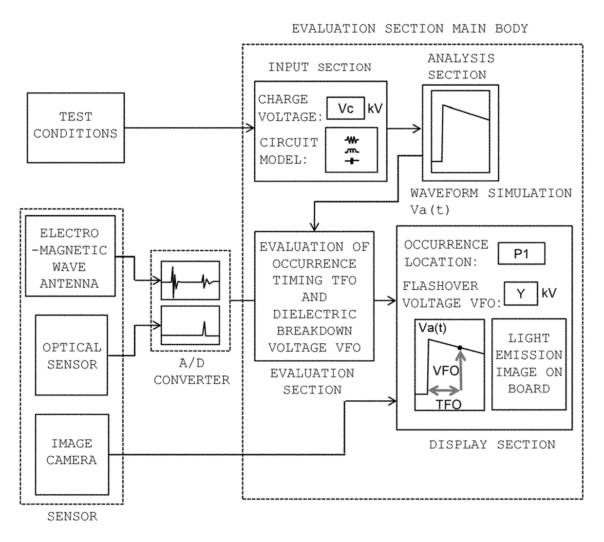
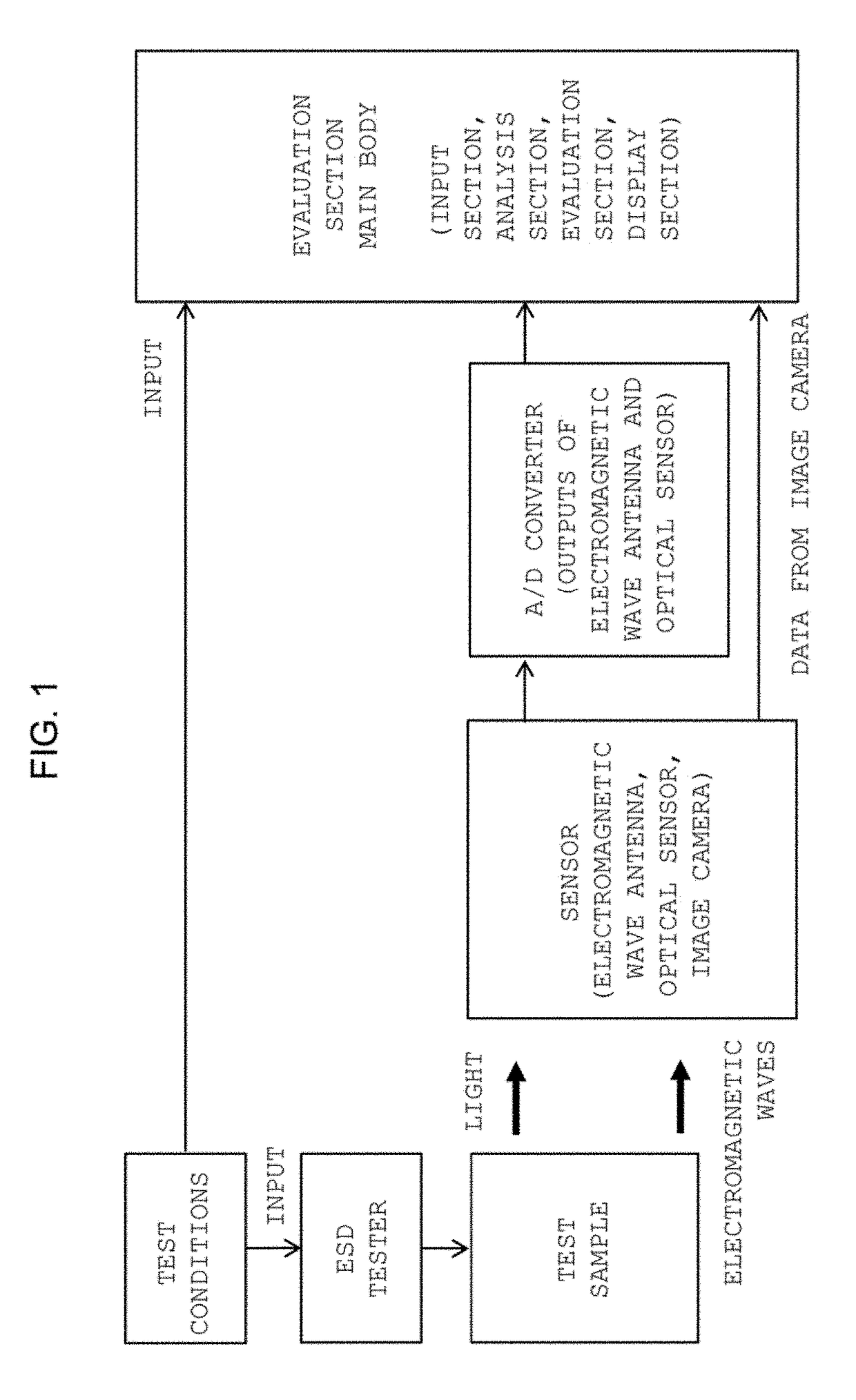
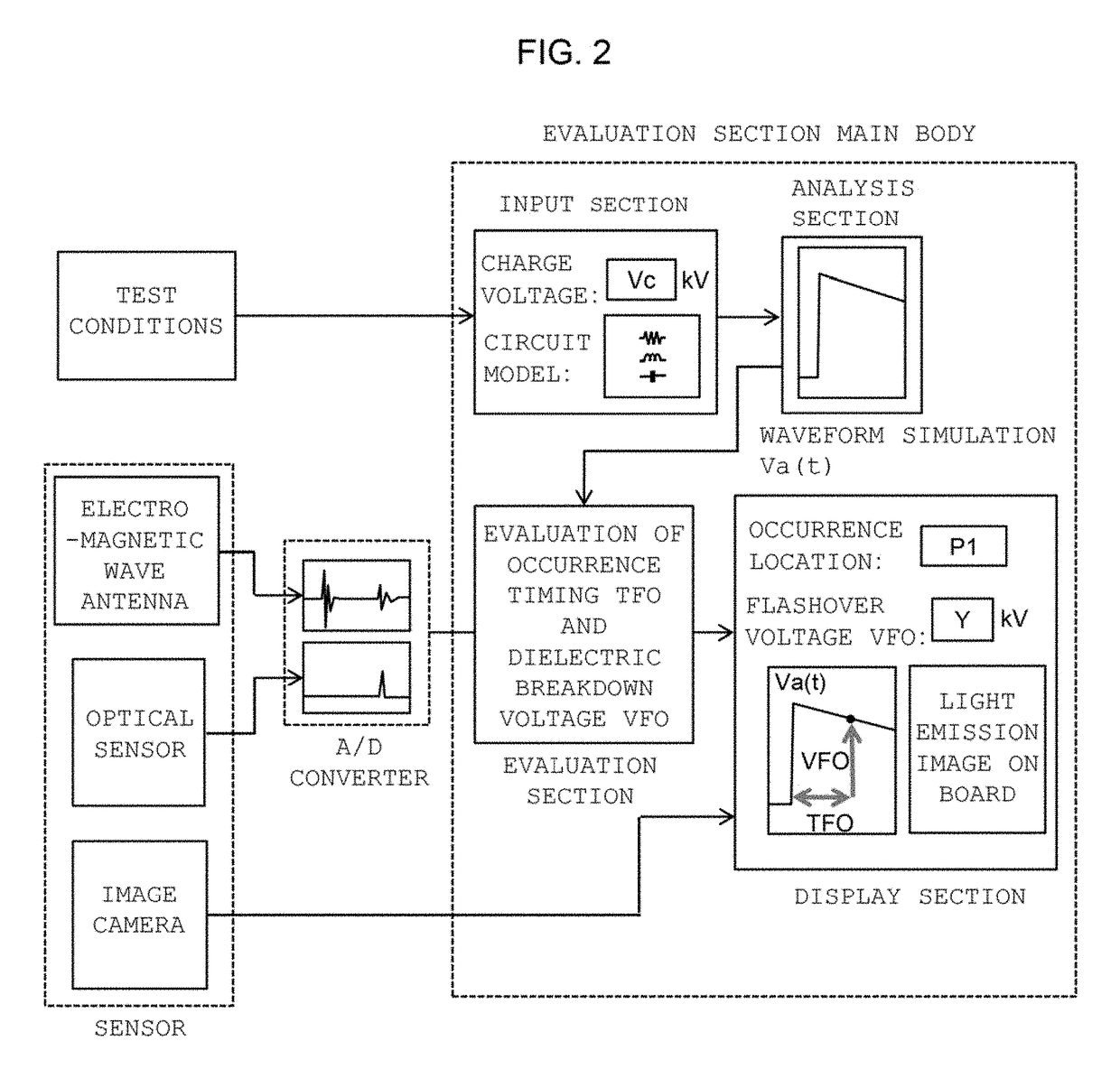
[0027]The present invention will be described by way of example. FIG. 1 is a schematic diagram of a discharge occurrence status evaluation device according to an embodiment of the present invention. A charge voltage Vc is input to an electrostatic discharge ESD tester as a test condition. Along with this charge voltage Vc, various conditions which constitute an electric circuit, such as the CR circuit conditions (resistor R and capacitor C) of the electrostatic discharge ESD tester and the circuit conditions of a to-be-tested board (the shape and length of wiring, gap condition, disposed components, etc.), are also sent to the evaluation section main body as test conditions. The electrostatic discharge ESD tester generates a voltage having an impulse-shaped waveform on the basis of the test conditions, and the evaluation section main body simulates the waveform of the impulse voltage applied to the test sample, on the basis of the test conditions and the electrical circuit condition...


PUM


Abstract

The present invention evaluates the status of discharge or dielectric breakdown having occurred as a result of application of an impulse voltage or current to a test sample by an electrostatic discharge tester. An electromagnetic wave antenna measures a radiation electromagnetic wave signal generated from the electrostatic discharge tester when the electrostatic discharge tester is driven and a radiation electromagnetic wave signal generated from the test sample when discharge or dielectric breakdown occurs. An evaluation section main body obtains and displays a dielectric breakdown occurrence timing TFO after application of the voltage and a dielectric breakdown voltage VFO. The dielectric breakdown occurrence timing TFO is obtained from the time difference between an applied voltage generation time obtained from the radiation electromagnetic wave signal generated when the electrostatic discharge tester was driven and a discharge generation time obtained from the radiation electromagnetic wave signal generated when dielectric breakdown occurred.

Description

[0001]This application claims the benefit of PCT International Application Number PCT / JP2013 / 082668 filed Dec. 5, 2013 and Japanese Application No. 2013-090307 filed, Apr. 23, 2013 in Japan, the disclosures of which are incorporated herein by reference.TECHNICAL FIELD[0002]The present invention relates to a discharge occurrence status evaluation device and an evaluation method for evaluating the status of discharge or dielectric breakdown having occurred as a result of application of an impulse voltage or current to a test sample by an electrostatic discharge tester.BACKGROUND ART[0003]Recent electrostatic discharge test apparatuses have a function of reporting occurrence of gaseous discharge. For example, Non-Patent Document 1 includes a description regarding an electrostatic tester having a “discharge detection function” of checking whether or not gaseous discharge has occurred. However, mere use of this discharge detection function does not allow us to know the timing at which di...

Claims


Application Information

Patent Timeline
Patent Type & Authority Patents(United States)
IPC IPC(8): G01R31/12G01R31/00G01R31/08
CPCG01R31/08G01R31/001G01R31/1218G01R31/1263
Inventor OHTSUKA, SHINYATSUBOI, KOTAROIWAI, SHO
Owner NAT UNIV CORP KYUSHU INST OF TECH (JP)
Why Eureka
Try Eureka