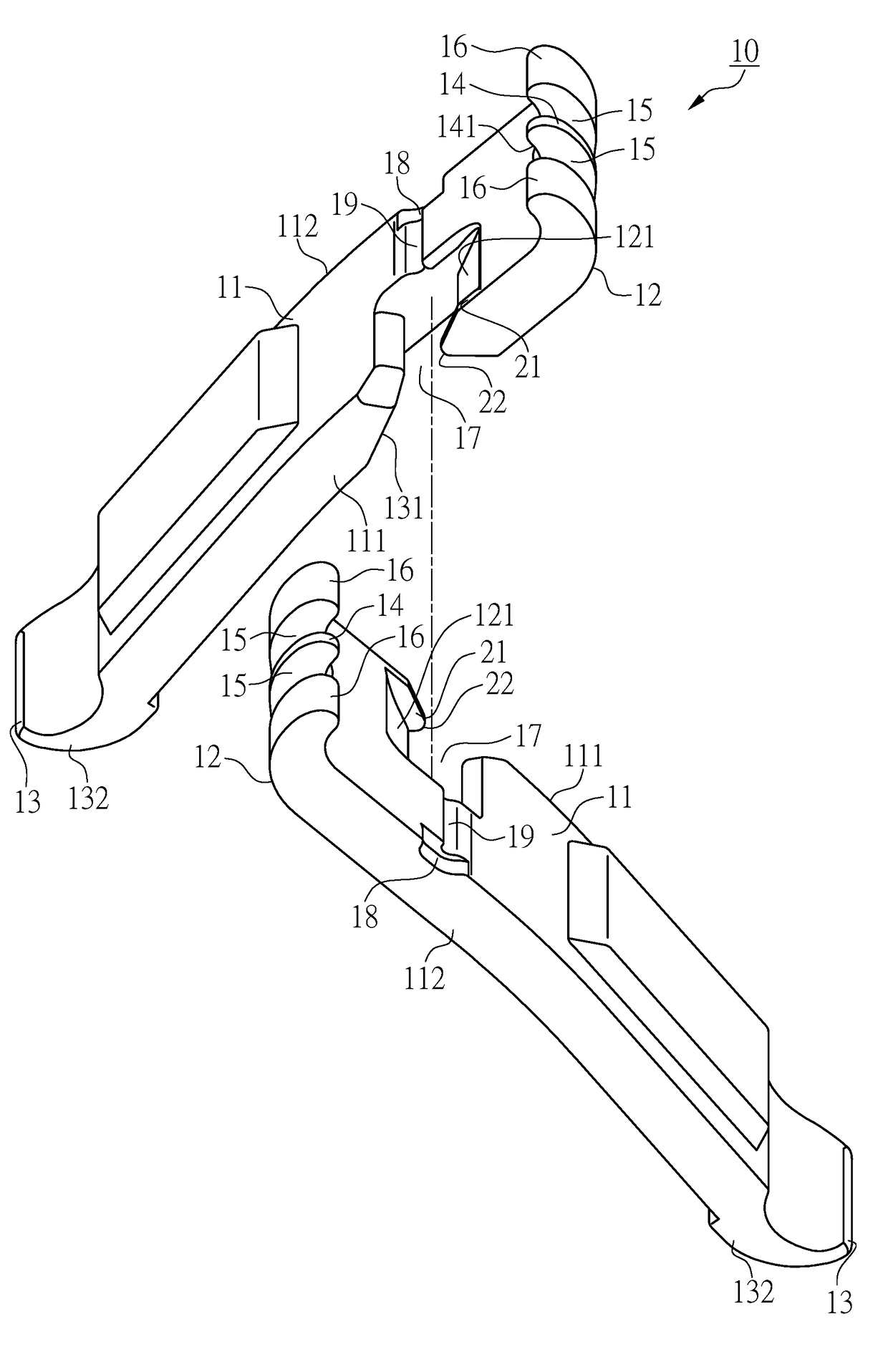
Chain tool

a chain tool and tool body technology, applied in the direction of metal chainmaking tools, chain/belt transmission, metal chains, etc., can solve the problems of disadvantageous single-handed operation, inability to carry a large number of tools, bulky tools such as pliers, etc., and achieve the effect of being operated single-handedly

Active Publication Date: 2018-07-31
BIB CREATIVE CO LTD
View PDF4 Cites 4 Cited by
  • Summary
  • Abstract
  • Description
  • Claims
  • Application Information

AI Technical Summary

Benefits of technology

[0008]The primary objective of the present invention is to provide a portable chain tool that can be operated single-handedly.

Problems solved by technology

In bicycle riding, however, a rider would generally desire to carry as little load as possible during cycling; hence it is practically impossible for a cyclist to carry with them a large number of tools or a bulky tool like pliers.
More specifically, the two plate-shaped members are engaged with each other via the openings only, without any securing structure between the openings; as a result, the two plate-shaped members tend to separate from each other in the assembled (i.e., engaged) state, which is disadvantageous to single-handed operation.

Method used


Image

  • Chain tool
  • Chain tool
  • Chain tool

Examples


second embodiment

[0043]When the chain tool in the second embodiment is used to disconnect the chain 30, referring to FIG. 11, the two members 41 are brought close to each other, with the first hook portion 44 and the second hook portion 45 of each member 41 facing their counterparts of the other member 41. Next, the two members 41 are engaged with each other through the openings 47 so as to be pivoted with respect to each other. The second hook portion 45 of one member 41 is then placed into the space between the pair of inner plates 32 located on one outer side of the quick link plates 33 and is pressed against one of the two rollers 35 corresponding to the quick link plates 33. Similarly, the second hook portion 45 of the other member 41 is placed into the space between the pair of inner plates 32 located on the other outer side of the quick link plates 33 and is pressed against the other of the two rollers 35 corresponding to the quick link plates 33. After that, a force is applied to the two mem...

first embodiment

[0045]As stated above, during the connecting process of the chain 30, the first hook portion 44 of one member 41 is placed in between the pair of quick link plates 33 and pressed against one of the two rollers 35 corresponding to the quick link plates 33, and the second hook portion 45 of the other member 41 is placed in between the pair of inner plates 32 located on one outer side of the quick link plates 33 and pressed against another roller 35. As the first hook portion 44 and the second hook portion 45 in use are close to each other while connecting the chain 30, the lateral component force actually provided by the two members 41 to move the two rollers 35 away from each other is so large as to not only produce the same effect as the first embodiment, but also make it possible to generate a sufficiently large lateral component force by applying a relatively small force when trying to moving the two rollers 35 away from each other. Thus, the present invention saves time and effor...


PUM


Abstract

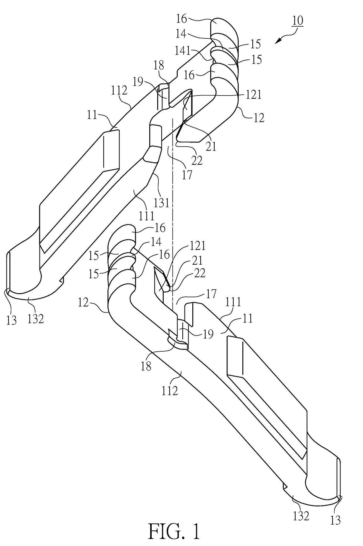
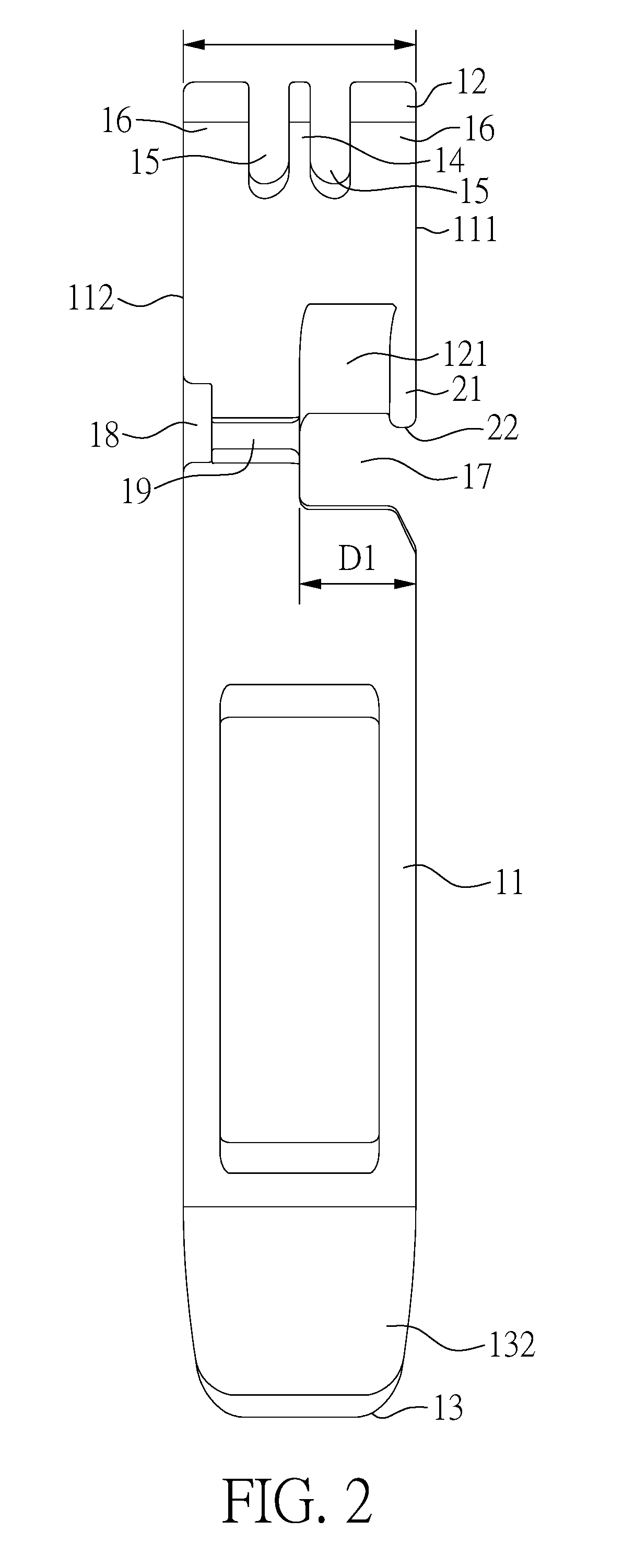
A chain tool has two members each having a first edge formed with an opening to be engaged with the opening of the other member so that the two members can be pivoted with respect to each other. Each member has an opposite second edge provided with a recess and also has a guide groove in communication with the recess and the corresponding opening, wherein the recess is lightly deeper than the guide groove. Each member further has a rib extending along the corresponding first edge and projecting into the corresponding opening to form a protruding portion. When the openings of the two members are brought into engagement, the protruding portion of each member is moved along the guide groove of the other member into engagement in the recess of the other member.

Description

BACKGROUND OF THE INVENTION[0001]1. Technical Field[0002]The present invention relates to the structure of a hand tool for connecting and disconnecting a chain. More particularly, the invention relates to a chain tool that is both portable and easy to use.[0003]2. Description of Related Art[0004]FIG. 21 shows a conventional chain 9 with rapidly connectable and disconnectable end links. The two end links of the chain 9 are provided with two outer plates 91 on two opposite sides of the chain 9 respectively. Each outer plate 91 has a pin 92 and a through hole 93, wherein the through hole 93 has a large-diameter section 931 and a small-diameter section 932.[0005]To connect the two end links of the chain 9 with the two outer plates 91, the pin 92 of each outer plate 91 is placed into the large-diameter section 931 of the through hole 93 of the other outer plate 91 through the corresponding hole in the corresponding end link. Then, the two end links are pulled in opposite directions so th...

Claims


Application Information

Patent Timeline
Patent Type & Authority Patents(United States)
IPC IPC(8): B21L21/00B25B27/00B62M9/16B25B27/22
CPCB25B27/22B62M9/16B25B27/0071B25B27/14
Inventor ICHIKAWA, TOMONARI
Owner BIB CREATIVE CO LTD
Why Eureka
Try Eureka