Thermal flow sensor for determining a gas or the composition of a gas mixture as well as its flow velocity

Active Publication Date: 2018-10-16
INNOVATIVE SENSOR TECH IST
View PDF11 Cites 0 Cited by
  • Summary
  • Abstract
  • Description
  • Claims
  • Application Information

AI Technical Summary

Benefits of technology

[0005]The object of this invention is therefore to propose a

Problems solved by technology

Since for physical reasons thermal flow sensors also react to thermal characteristics of the gas in which they are used in addition to the flow velocity, an exact or precise determination of the flow velocity is no longer possible when the thermal characteristics of the gas change.
This disadvantage i

Method used


Image

  • Thermal flow sensor for determining a gas or the composition of a gas mixture as well as its flow velocity
  • Thermal flow sensor for determining a gas or the composition of a gas mixture as well as its flow velocity
  • Thermal flow sensor for determining a gas or the composition of a gas mixture as well as its flow velocity

Examples


Example

DETAILED DISCUSSION IN CONJUNCTION WITH THE DRAWINGS

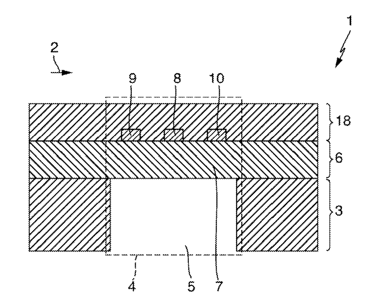
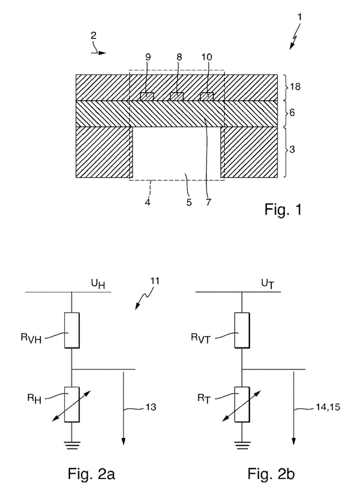
[0037]FIG. 1 shows a cross-section of an embodiment of the flow sensor 1 according to the invention. The thermal flow sensor 1 features a substrate 3 onto which a first dielectric layer 6 is applied. The substrate 3 further features a recess 5 in a first area 4 so that the first dielectric layer generates a membrane 7 in the first area 4 on the substrate 3. A heating structure 8 is applied onto the membrane 7 in such a way that it is between a first and second temperature sensor element 9, 10 along the flow direction of the gas or the gas mixture 2 and serves to heat the gas or gas mixture 2. The two temperature sensor elements 9, 10 are also applied onto the first dielectric layers 6 and preferably arranged in such a way that they are in the first area 4. Those two temperature sensor elements 9, 10 serve to capture the temperature of the gas or gas mixture 2 heated at the heating structure 8. In order to protect the heating struct...


PUM


Abstract

A thermal flow sensor for determining a gas or the composition of a gas mixture as well as its flow velocity, comprising: a substrate onto which at least a first dielectric layer is applied; at least one heating structure that is applied onto the first dielectric layer and serves to heat the gas or the gas mixture; at least a first temperature sensor element that is applied onto the first dielectric layer at a distance from the heating structure and captures the temperature of the gas or gas mixture heated at the heating structure; a control device that controls the heating structure in a first operating mode in such a way that the heating structure shows a predetermined temperature, and controls the heating structure in a second operating mode in such a way that a power input into the heating structure corresponds to a predetermined power; and an evaluation unit which determines at least one physical characteristic of the gas present or the gas mixture on the basis of the operating modes and determines the gas present or the composition of the gas mixture as well as its flow velocity on the basis of this physical characteristic.

Description

TECHNICAL FIELD[0001]The invention refers to a thermal flow sensor that serves to determine a gas or the composition of a gas mixture as well as its flow velocity.BACKGROUND DISCUSSION[0002]Thermal flow sensors are well-known from the current state of the art. Such sensors are, for example, used to determine the flow velocity of a gas. Since for physical reasons thermal flow sensors also react to thermal characteristics of the gas in which they are used in addition to the flow velocity, an exact or precise determination of the flow velocity is no longer possible when the thermal characteristics of the gas change. Such changes in the thermal characteristics may occur during the measuring operation of a flow sensor if, for example, the composition of a gas mixture or the gas itself changes.[0003]This disadvantage is compensated by a recalibration of the thermal flow sensor used. This is typically done by introducing another sensor that identifies the gas present and / or the composition...

Claims


Application Information

Patent Timeline
IPC IPC(8): G01N25/00G01F1/68G01N33/00G01F1/692G01F1/699
CPCG01N25/00G01F1/68G01N33/0027G01F1/699G01F1/692
Inventor HEPP, CHRISTOPHKROGMANN, FLORIAN
Owner INNOVATIVE SENSOR TECH IST
Why Eureka
Try Eureka