Connector for butt-connecting two components

Active Publication Date: 2020-07-16
HOFELE GMBH & CO KG
View PDF0 Cites 1 Cited by
  • Summary
  • Abstract
  • Description
  • Claims
  • Application Information

AI Technical Summary

Benefits of technology

The invention reduces the connecting force between components by up to 50%, which negatively impacts the practical application of the invention. However, this reduction in connecting force results in a simplified and user-friendlier connection method, as the components only require a simple compression / pushing together, instead of a blow. This change in the connection method also reduces deformation of the front plug-in portions, making the components easier to connect.

Problems solved by technology

It has been shown, however, that the connecting forces which are necessary in the moving together of the two chipboards are very high, and the components to be connected are not always fixed to one another in a gap-free manner.
It has further been shown that chipboards are often too soft to bring about a compression of the cone, above all on the end face.
However, this engenders a large force requirement in the connecting together of the chipboards, which has a negative effect on the practical application.
It has been shown that this desired deformation of the connector, however, likewise calls for a large force requirement.

Method used


Image

  • Connector for butt-connecting two components
  • Connector for butt-connecting two components
  • Connector for butt-connecting two components

Examples


Embodiment Construction

[0026]In the following description of the figures, for same structural parts, or structural parts having the same function, identical reference symbols are used.

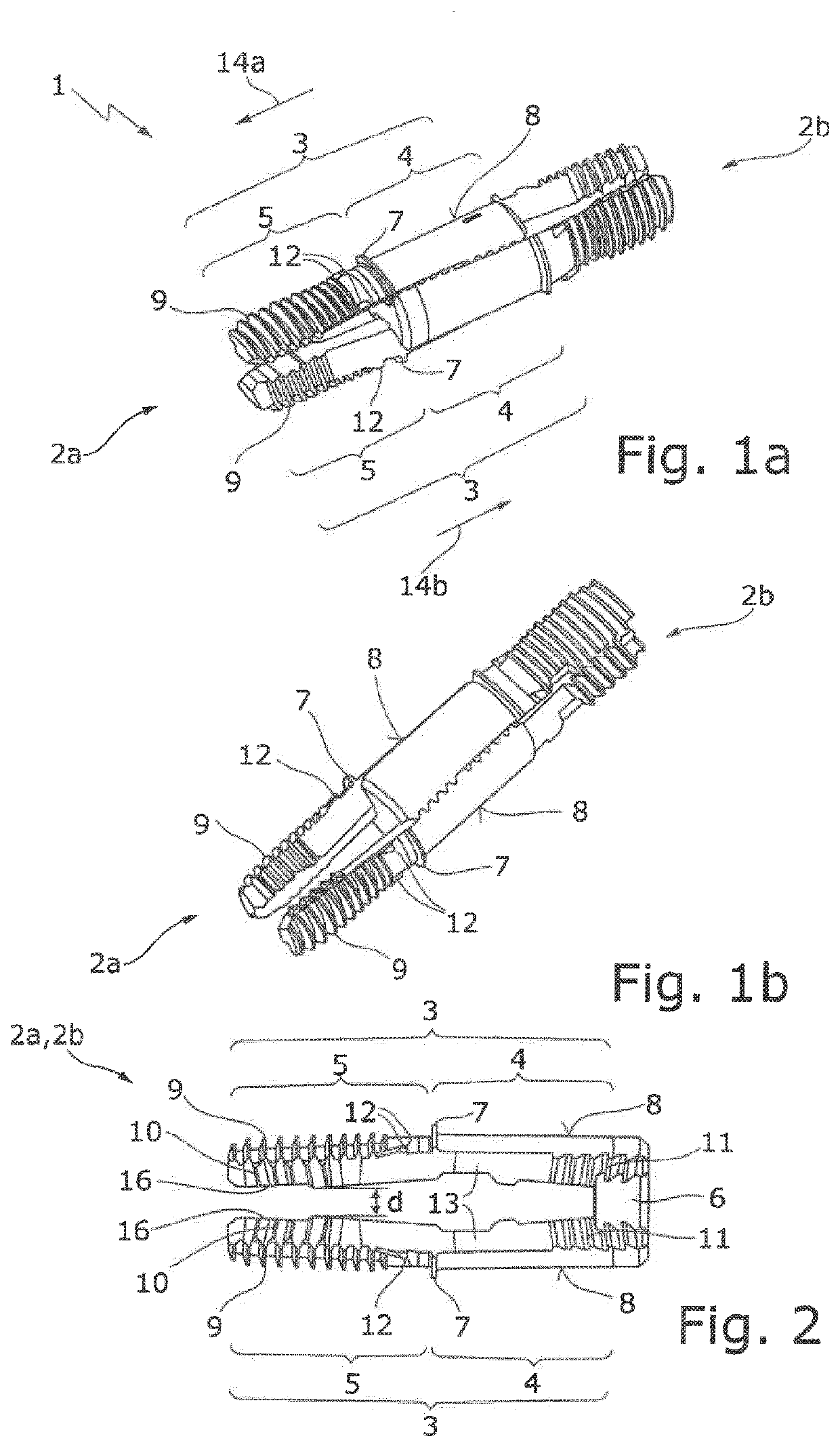
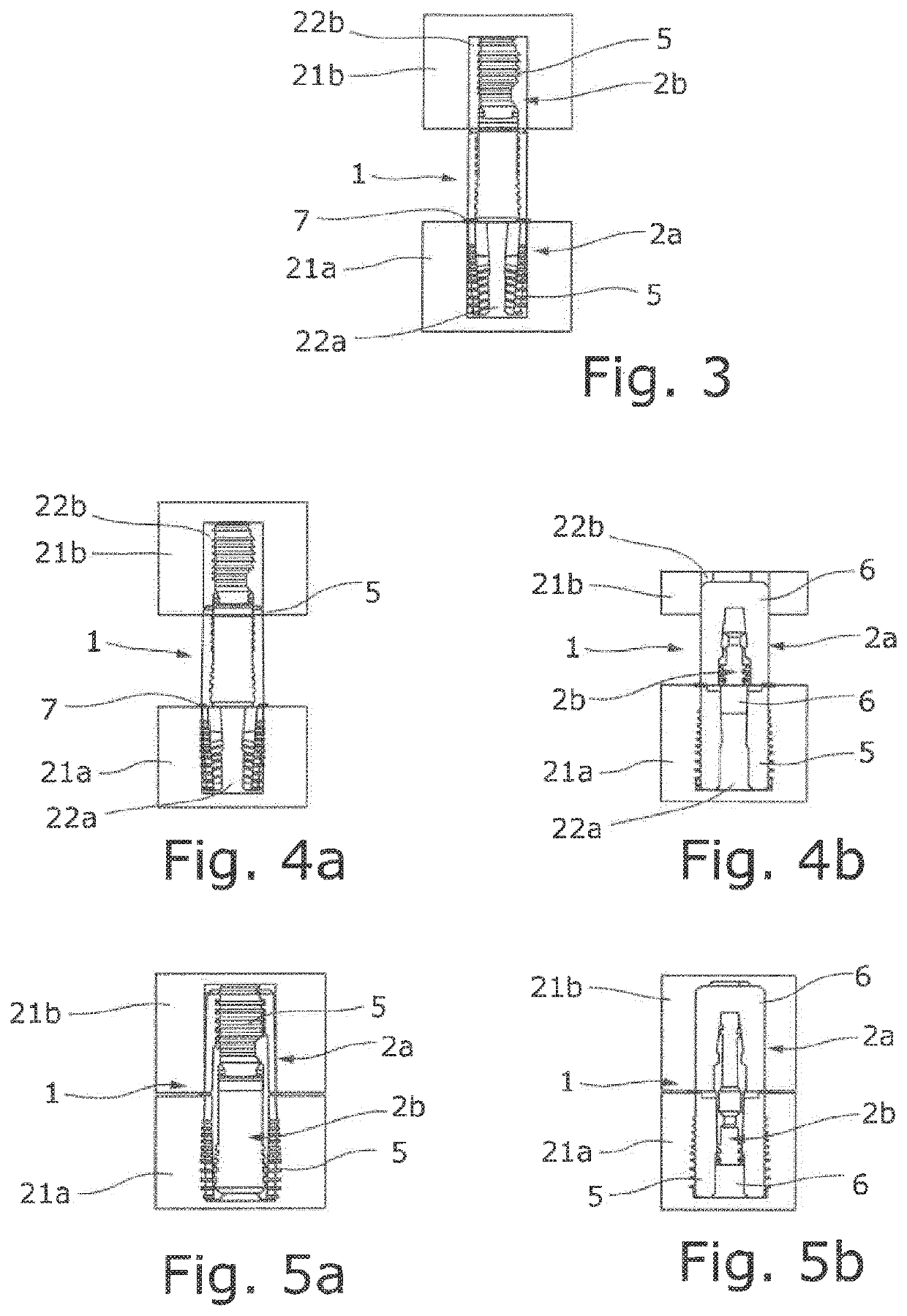
[0027]The connector 1 shown in FIGS. 1a and 1b serves for the butt-connecting of two chipboards 21a, 21b in a T-joint (FIG. 3), which chipboards respectively have a circular drill hole 22a, 22b. The chipboards 21a, 21b have, except for the soft end faces, a hard surface, so that, in the T-joint, a soft chipboard end face abuts a hard surface.

[0028]The connector 1 comprises two connector parts, in the form of U-shaped brackets 2a, 2b, which in the shown illustrative embodiment are of structurally identical configuration, but can also be of different configuration.

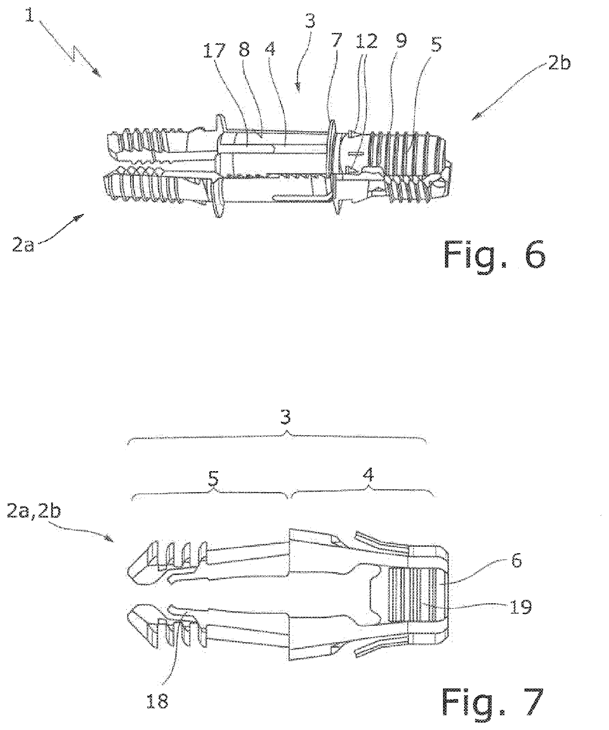
[0029]As shown in FIG. 2, the U-shaped bracket 2a, 2b comprises two outer bracket arms 3, having respectively a rear plug-in portion 4 and having a front plug-in portion 5 forming the free bracket end, as well as an interjacent middle bracket arm 6. The two outer bra...


PUM


Abstract

A connector for butt-connecting two chipboard components having two connector parts, which, mutually rotated through 90°, can be pushed together, into one another, into a locked assembly position and are in the form of U-shaped brackets having two outer bracket arms, which respectively have a rear plug-in portion for insertion into a circular drill hole of one component and an expandable front plug-in portion, forming the free bracket end, for insertion into a circular drill hole of the other component. A middle bracket arm is for expansion of the two front plug-in portions of the respectively other bracket in the assembly position. At least one locking portion for the mutual locking of the two brackets in the assembly position is provided. The outer sides of the rear plug-in portions are each configured, at least approximately, as partial lateral surfaces of the same circular cylinder.

Description

CROSS-REFERENCE FOR RELATED APPLICATIONS[0001]This continuation application claims priority to PCT / EP2018 / 073602 filed on Sep. 3, 2018, which has published as WO 2019 / 068401 A1, and also the German application number 20 2017 106 045.4 filed on Oct. 5, 2017, the entire contents of which are fully incorporated herein with these references.DESCRIPTIONField of the Invention[0002]The invention relates to a connector for butt-connecting two components, comprising two connector parts, in the form of U-shaped brackets, which can be pushed together into one another into a locked assembly position, according to the preamble of claim 1, and to an arrangement comprising such a connector.Background of the Invention[0003]A connector of this type has been disclosed, for instance, by DE 20 2016 102 176 U1.[0004]Preferably, such connectors consist of plastic which is deformable in a resiliently elastic manner and which has comparatively good sliding characteristics. The connection can here made betw...

Claims


Application Information

Patent Timeline
IPC IPC(8): F16B33/02
CPCF16B33/02F16B5/0024F16B12/20F16B12/26F16B13/128F16B21/082F16B12/24
Inventor VON WILCKE, MICHAELLEISTERT, PEERSAWATZKI, GERDNITSCHMANN, GUNTER
Owner HOFELE GMBH & CO KG
Why Eureka
Try Eureka