
Use of wheel slip to help identify soft spots

a technology of soft spot identification and wheel slip, which is applied in the field of identification and mapping of soft spot, can solve the problems safety hazards, and soft spot appearing on the surface being compacted, and achieves the effects of reducing vehicle traction, reducing safety hazards, and reducing vehicle traction

Active Publication Date: 2018-10-30
CATERPILLAR PAVING PROD INC
View PDF18 Cites 90 Cited by
  • Summary
  • Abstract
  • Description
  • Claims
  • Application Information

AI Technical Summary

Benefits of technology

Enables quick and accurate repair of soft spots by providing real-time location data to operators and supervisors, reducing search time and costs by precisely identifying the location of soft spots.

Problems solved by technology

Despite the use of a compactor, soft spots may occur in a surface that is being compacted.
Soft spots may create safety hazards, reduce vehicle traction or preclude a stable foundation with a known and uniform density.
However, because soft spots may not be clearly visible, precisely locating a soft spot that has been traversed by a compactor remains problematic because there is no convenient means for recording the precise location of a soft spot or transmitting the precise location of a soft spot to a repair crew.

Method used


Image

  • Use of wheel slip to help identify soft spots
  • Use of wheel slip to help identify soft spots
  • Use of wheel slip to help identify soft spots

Examples


Embodiment Construction

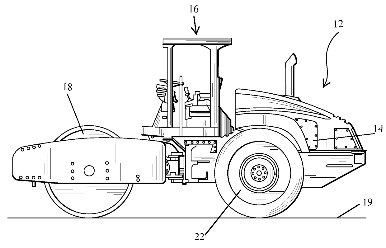
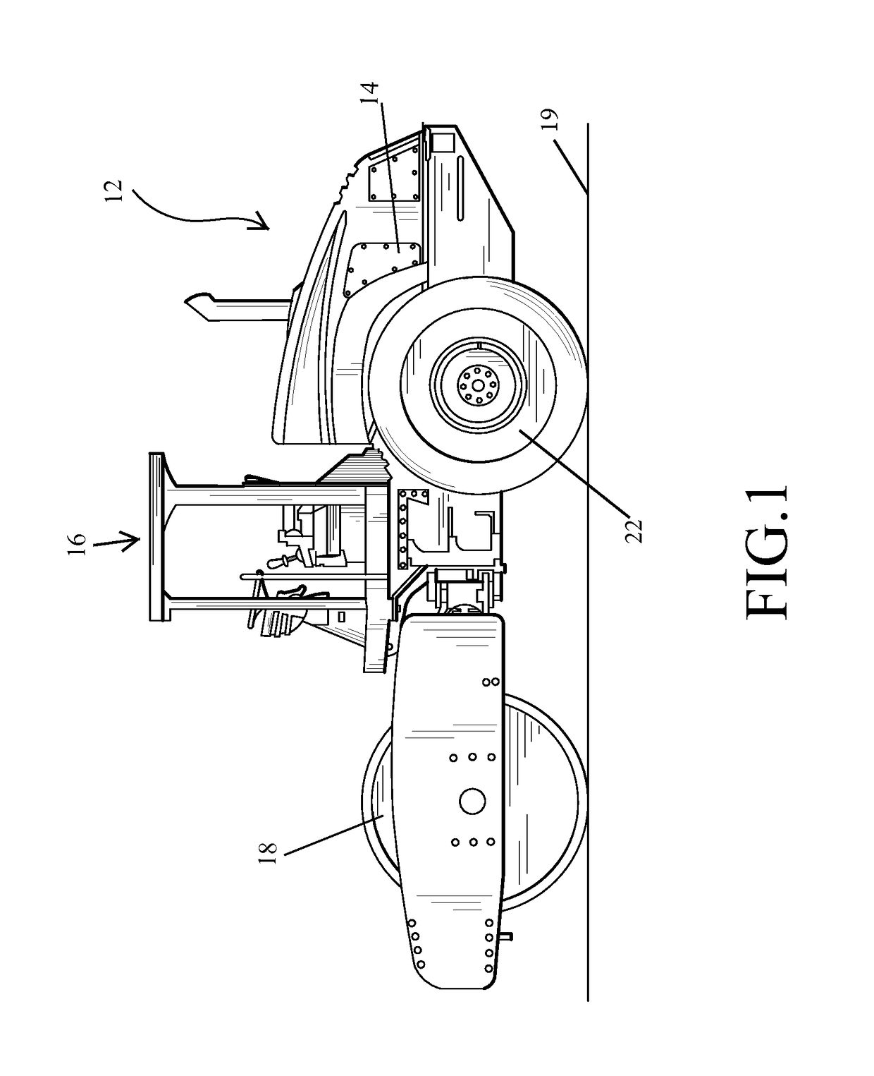
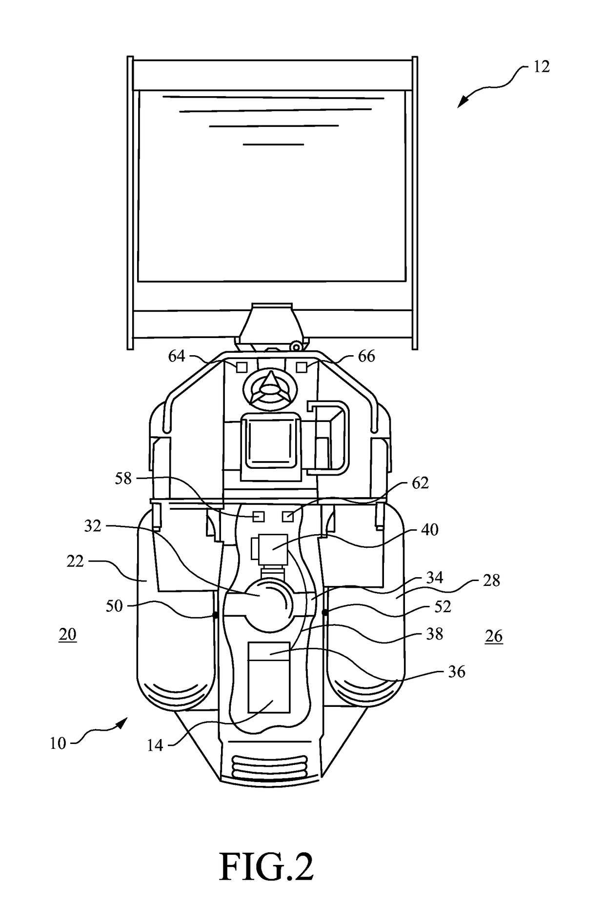
[0015]FIG. 1 illustrates a compactor 12, which may include an engine 14, a cab 16 and a drum 18. In an exemplary embodiment, compactor 12 is a soil compactor. In alternative embodiments, compactor 12 may be any other compactor having wheels, such as a landfill compactor. The drum 18 is located forward of the cab 16 and rotates as the compactor 12 rolls over a surface 19. The cab 16 may include various controls for an operator. As shown in FIG. 2, the compactor 12 may also include a first side 20 with a first wheel 22 and a second side 26 with a second wheel 28.

[0016]As further shown in FIG. 2, the compactor 12 may include a differential 32 coupled to an axle 34, which may distribute power to one or both wheels 22, 28 from the differential 32. The engine 14 may power a hydraulic pump 36 that drives a primary hydraulic motor 40 for transmitting hydraulic power to the differential 32 and one or both of the wheels 22, 28. The engine 14 may also provide power to the differential 32 throu...


PUM

PropertyMeasurementUnit
rotational speedaaaaaaaaaa
rotational velocityaaaaaaaaaa
structural stabilityaaaaaaaaaa

Abstract

A compactor gathers GPS, orientation and wheel slip data to identify the location of a soft spot in a surface that is being compacted and to isolate the soft spot to a particular side of the compactor if the wheel slip data indicates that the soft spot is located beneath only one of the compactor wheels. The GPS, orientation and wheel slip data are displayed as location information to an operator and / or sent to a remote location to facilitate the fast and accurate repair of the soft spot.

Description

TECHNICAL FIELD[0001]This disclosure relates to compaction machines or compactors. More particularly, this disclosure relates to the identification and mapping of soft spots in the surface or material being compacted by compactors.BACKGROUND[0002]Compactors are used for compacting various surfaces and materials associated with roads, landfills and construction sites. For example, road builders use compactors to compact asphalt, soil, gravel and other materials during road construction and repair. Thorough compaction of the underlying ground and each layer of a road provides the requisite structural stability for the road. Landfill operators use compactors to maximize the use of a landfill by compacting trash to create space for additional trash. Compacting the trash in a landfill also helps to increase the structural stability of the landfill.[0003]One type of compactor is a drum-type compactor having a heavy rotating drum for compacting or crushing the material over which the compa...

Claims


Application Information

Patent Timeline
Patent Type & Authority Patents(United States)
IPC IPC(8): G01L11/00G01S19/13G01S19/39G01S19/14
CPCG01S19/14G01S19/13G01L11/00G01S19/39E01C19/26E01C19/288
Inventor FRELICH, THOMAS J.HENDRICKS, KYLE DAVID
Owner CATERPILLAR PAVING PROD INC
Learn More