Surveillance apparatus having an optical camera and a radar sensor

a technology of optical camera and radar sensor, which is applied in the field of surveillance cameras, can solve the problems of system visual impairment, optical surveillance camera image impairment, optical surveillance camera vulnerability to optical system attacks, etc., and achieve the effect of expanding surveillance capabilities and efficiently and flexibly monitoring

Active Publication Date: 2018-12-18
SONY CORP
View PDF15 Cites 1 Cited by
  • Summary
  • Abstract
  • Description
  • Claims
  • Application Information

AI Technical Summary

Benefits of technology

[0011]It is an object of the present disclosure to provide a surveillance apparatus and a corresponding surveillance method which overcome the above-mentioned drawbacks. It is a further object to provide a corresponding computer program and a non-transitory computer-readable recording medium for implementing said method. In particular, it is an object to expand the surveillance capabilities to measurement scenarios where a purely optical camera fails and to efficiently and flexibly monitor a desired field of view.
[0029]The surveillance apparatus according to the present disclosure uses a different approach by combining an optical camera that captures images based on received light, and a radar sensor, that emits and receives electromagnetic radiation. The optical camera has a first field of view and the radar sensor has a second field of view. The first field of view is variable with respect to the second field of view. Alternatively, the second field of view differs from the first field of view. For example, the first field of view of the optical camera covers an angular range of about 50-80° to avoid substantial image distortions, whereas the second field of view of the radar sensor covers an angular range of at least 90°, preferably 180°, or even a full 360°. Thus, the field of view of the radar sensor is larger than the field of view of the optical camera and thereby monitors a wider field of view. However, the information gained from the radar sensor is often not sufficient for surveillance applications since often a high-resolution optical image is desired. Therefore, the field of view of the optical camera is variable with respect to the field of view of the radar sensor. In particular, the size and / or orientation of the first field of view are variable with respect to the second field of view. For example, an object can be identified with the radar sensor and the field of view of the optical camera is adjusted to cover said object. This is particularly beneficial if an object that is initially not covered by the field of view of the optical camera is now detected in the field of view of the radar sensor.

Problems solved by technology

While optical surveillance cameras show very good performance under regular operating conditions, these systems are prone to visual impairments.
In particular, the images of optical surveillance cameras are impaired by smoke, dust, fog, fire and the like.
An optical surveillance camera is also vulnerable to attacks of the optical system, for example paint from a spray attack, stickers glued to the optical system, cardboard or paper obstructing the field of view, or simply a photograph that pretends that the expected scene is monitored.
Furthermore, the optical system can be attacked by laser pointers, by blinding the camera or by mechanical repositioning of the optical system.
However, this requires proper calibration of the optical surveillance cameras which is very complex, time consuming, and expensive.
Furthermore a stereoscopic camera system typically is significantly larger and more expensive compared to a monocular, single camera setup.
The field of view of an optical camera that captures images based on received light is typically limited to a confined angular range.
While such optical elements significantly broaden the field of view of the optical camera, they also create a significantly distorted image of the observed scene.
This makes image analyses difficult for an operator that monitors the images captured by the surveillance camera, if no additional correction and post-processing is applied.
However, the information gained from the radar sensor is often not sufficient for surveillance applications since often a high-resolution optical image is desired.

Method used


Image

  • Surveillance apparatus having an optical camera and a radar sensor
  • Surveillance apparatus having an optical camera and a radar sensor
  • Surveillance apparatus having an optical camera and a radar sensor

Examples


embodiment 1

2. The surveillance apparatus ,

wherein size and / or orientation of said first field of view are variable with respect to said second field of view.

3. The surveillance apparatus according to any preceding embodiment,

wherein said optical camera is movable with respect to the radar sensor.

4. The surveillance apparatus according to any preceding embodiment,

further comprising a control unit that controls the optical camera based on radar information obtained with the radar sensor.

5. The surveillance apparatus according to any preceding embodiment,

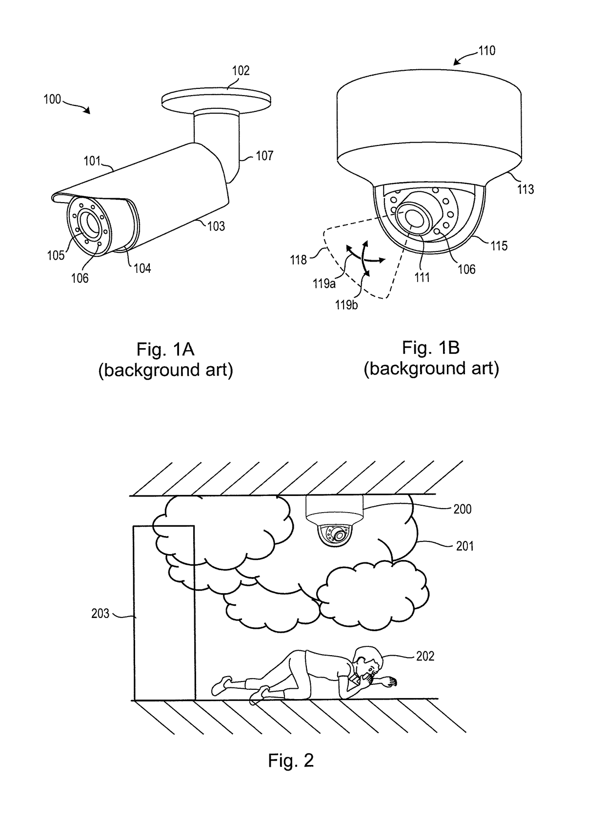
wherein the optical camera further comprises a translucent camera cover.

embodiment 5

6. The surveillance apparatus ,

wherein the camera cover comprises a substantially hemispheric camera dome.

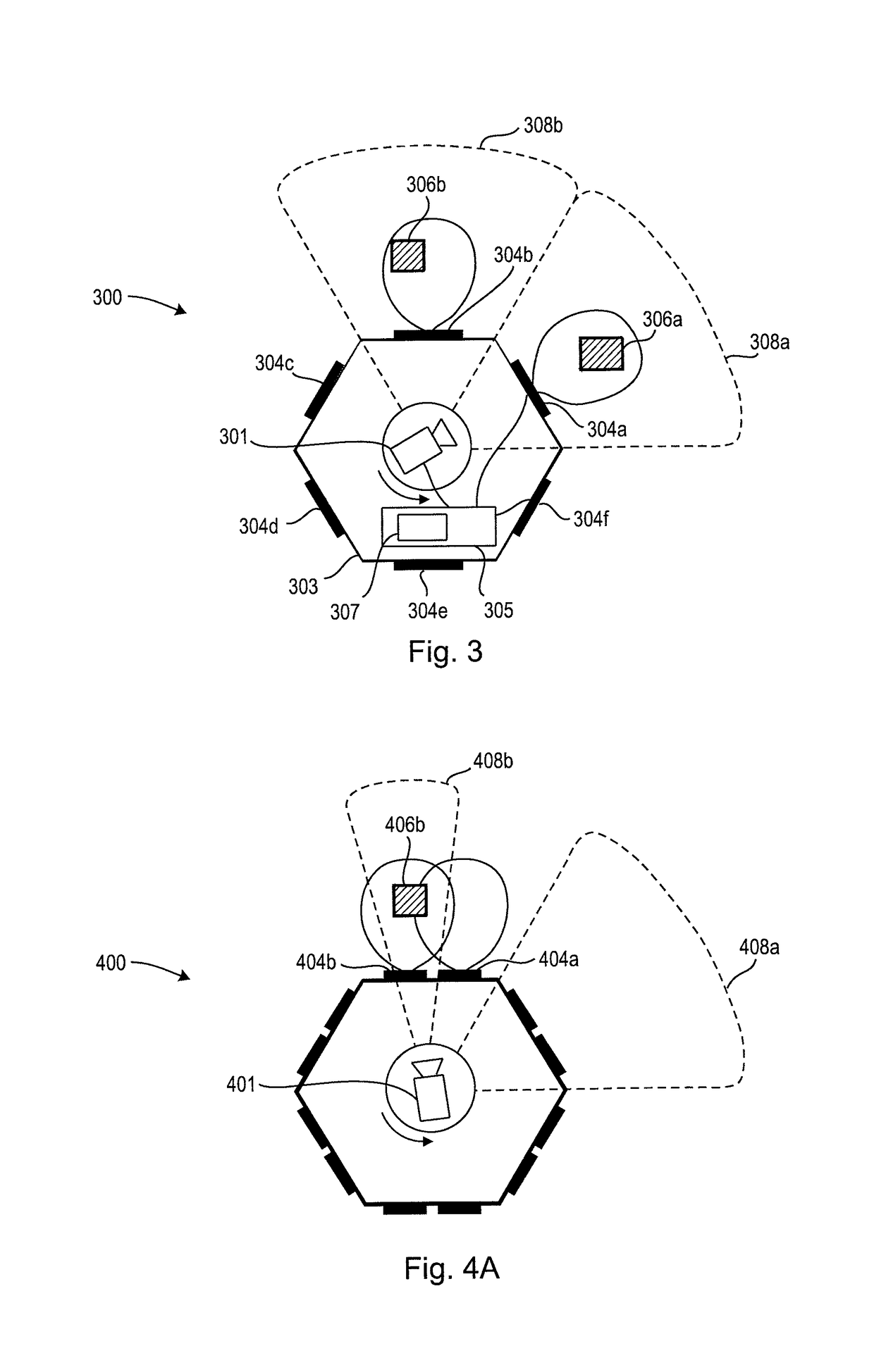
7. The surveillance apparatus according to any preceding embodiment,

having a polygonal, cylindrical or circular outline.

8. The surveillance apparatus according to any preceding embodiment,

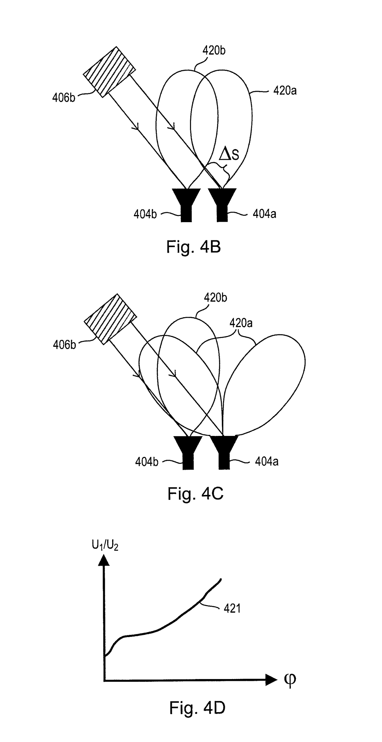
wherein the radar sensor comprises an antenna element arranged on the periphery of the surveillance apparatus.

9. The surveillance apparatus according to any preceding embodiment,

wherein the radar sensor is adapted to provide at least one of a direction, range and speed of an object relative to the surveillance apparatus.

10. The surveillance apparatus according to embodiment 5,

wherein the camera cover further comprises a translucent antenna.

embodiment 10

11. The surveillance apparatus ,

wherein the translucent antenna comprises an electrically conductive layer comprising at least one of a translucent electrically conductive material and an electrically conductive mesh structure.


PUM


Abstract

A surveillance apparatus, a corresponding method, surveillance radar apparatus, computer program, and non-transitory computer-readable recording medium, the surveillance apparatus including an optical camera that captures images based on received light, the optical camera having a first field of view, a radar sensor that emits and receives electromagnetic radiation, the radar sensor having a second field of view, and wherein the first field of view is variable with respect to the second field of view.

Description

CROSS-REFERENCE TO RELATED APPLICATIONS[0001]The present application is based on PCT filing PCT / EP2014 / 058755 filed Apr. 29, 2014, and claims priority to European Patent Application 13 169 006.7, filed in the European Patent Office on May 23, 2013, the entire contents of each of which being incorporated herein by reference.BACKGROUND[0002]Field of the Disclosure[0003]The present disclosure relates to the field of surveillance cameras for safety and security applications. A surveillance apparatus, having an optical camera and an additional radar sensor, and a corresponding surveillance method are disclosed. Application scenarios include burglar, theft or intruder alarm as well as monitoring public and private areas.[0004]Description of Related Art[0005]Optical surveillance cameras are used in many public places such as train stations, stadiums, supermarkets and airports to prevent crimes or to identify criminals after they committed a crime. Optical surveillance cameras are widely us...

Claims


Application Information

Patent Timeline
Patent Type & Authority Patents(United States)
IPC IPC(8): G08B13/196G08B13/187
CPCG08B13/1963G08B13/187G08B13/19695G08B13/19619G08B13/19689
Inventor BLECH, MARCELBOEHNKE, RALFDAYI, FURKAN
Owner SONY CORP
Why Eureka
Try Eureka