Surveillance apparatus having an optical camera and a radar sensor

a technology of optical camera and radar sensor, which is applied in the direction of individually energised antenna arrays, instruments, and reradiation, etc., can solve the problems of optical surveillance camera image impairment, optical surveillance camera vulnerability to optical system attacks, and system visual impairment, so as to increase surveillance capabilities and efficiently and flexibly monitor

Active Publication Date: 2019-08-13
SONY CORP
View PDF29 Cites 2 Cited by
  • Summary
  • Abstract
  • Description
  • Claims
  • Application Information

AI Technical Summary

Benefits of technology

[0011]It is an object of the present disclosure to provide a surveillance apparatus and a corresponding surveillance method which overcome the above-mentioned drawbacks. It is a further object to provide a corresponding computer program and a non-transitory computer-readable recording medium for implementing said method. In particular, it is an object to expand the surveillance capabilities to measurement scenarios where a purely optical camera fails and to efficiently and flexibly monitor a desired field of view.
[0025]The integration of the antennas of the radar sensor into the surveillance apparatus as disclosed, for instance into the frame of the optical camera, has the effect that both the radar sensor and the optical camera substantially have the same field of view or at least “look” into the same direction and can simultaneously “see” the same scenery. This is achieved by providing that the center area, i.e. an area including and / or being located close to the center, of the optical aperture of the optical camera and the center area, i.e. an area including and / or being located close to the center, of the virtual antenna array coincide or are at least overlapping to a substantial extent.
[0027]This arrangement further enables that both the radar sensor and the optical camera may be moved together by movement elements, e.g. the mechanics, actuators or motors, which is already available for the optical camera, so that also during and after such a movement both the radar sensor and the optical camera look to the same scenery. No additional means is needed for the radar sensor to enable such a movement. In such a configuration, the radar sensor and the camera are preferably co-located and jointly moved. Therefore, no space / angle synchronization is needed for the data fusion from both the radar sensor and the camera. The radar sensor may have a fixed antenna beam, e.g. for range detection, or may employ a 1D or 2D antenna array for 1D or 2D beam forming, which provides the radar sensor with electrical angular scanning capability.

Problems solved by technology

While optical surveillance cameras show very good performance under regular operating conditions, these systems are prone to visual impairments.
In particular, the images of optical surveillance cameras are impaired by smoke, dust, fog, fire and the like.
An optical surveillance camera is also vulnerable to attacks of the optical system, for example paint from a spray attack, stickers glued to the optical system, cardboard or paper obstructing the field of view, or simply a photograph that pretends that the expected scene is monitored.
Furthermore, the optical system can be attacked by laser pointers, by blinding the camera or by mechanical repositioning of the optical system.
However, this requires proper calibration of the optical surveillance cameras which is very complex, time consuming, and expensive.
Furthermore a stereoscopic camera system typically is significantly larger and more expensive compared to a monocular, single camera setup.
Further, the range measurement accuracy is degrading with increased distance to the object, making stereoscopic camera based depth sensors useless for long range applications.

Method used


Image

  • Surveillance apparatus having an optical camera and a radar sensor
  • Surveillance apparatus having an optical camera and a radar sensor
  • Surveillance apparatus having an optical camera and a radar sensor

Examples


first embodiment

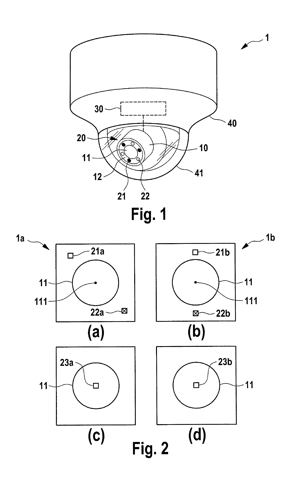
[0047]Referring now to the drawings, wherein like reference numerals designate identical or corresponding parts throughout the several views, FIG. 1 shows a surveillance apparatus 1 according to the present disclosure. It comprises an optical camera 10 configured to capture images based on received light, said optical camera 10 having a camera aperture 11. The surveillance apparatus 1 further comprises a radar sensor 20 having one or more (here three) transmitting antennas 21 (indicated by full circles) configured to emit electromagnetic radiation and one or more (here three) receiving antennas 22 (indicated by empty circles) configured to receive electromagnetic radiation. In this embodiment the antennas 21, 22 are arranged on the frame 12 of the camera 10 around the camera aperture 11. Due to their arrangement the antennas 21, 22 form a virtual antenna array, as will be explained in more detail below that is overlapping with the camera aperture 11.

[0048]The optical camera 10 is pr...

ninth embodiment

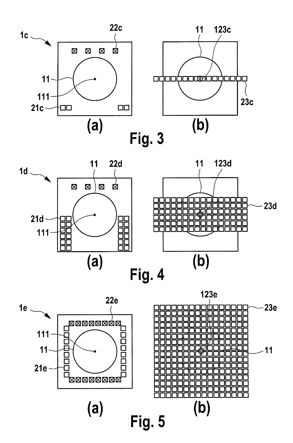
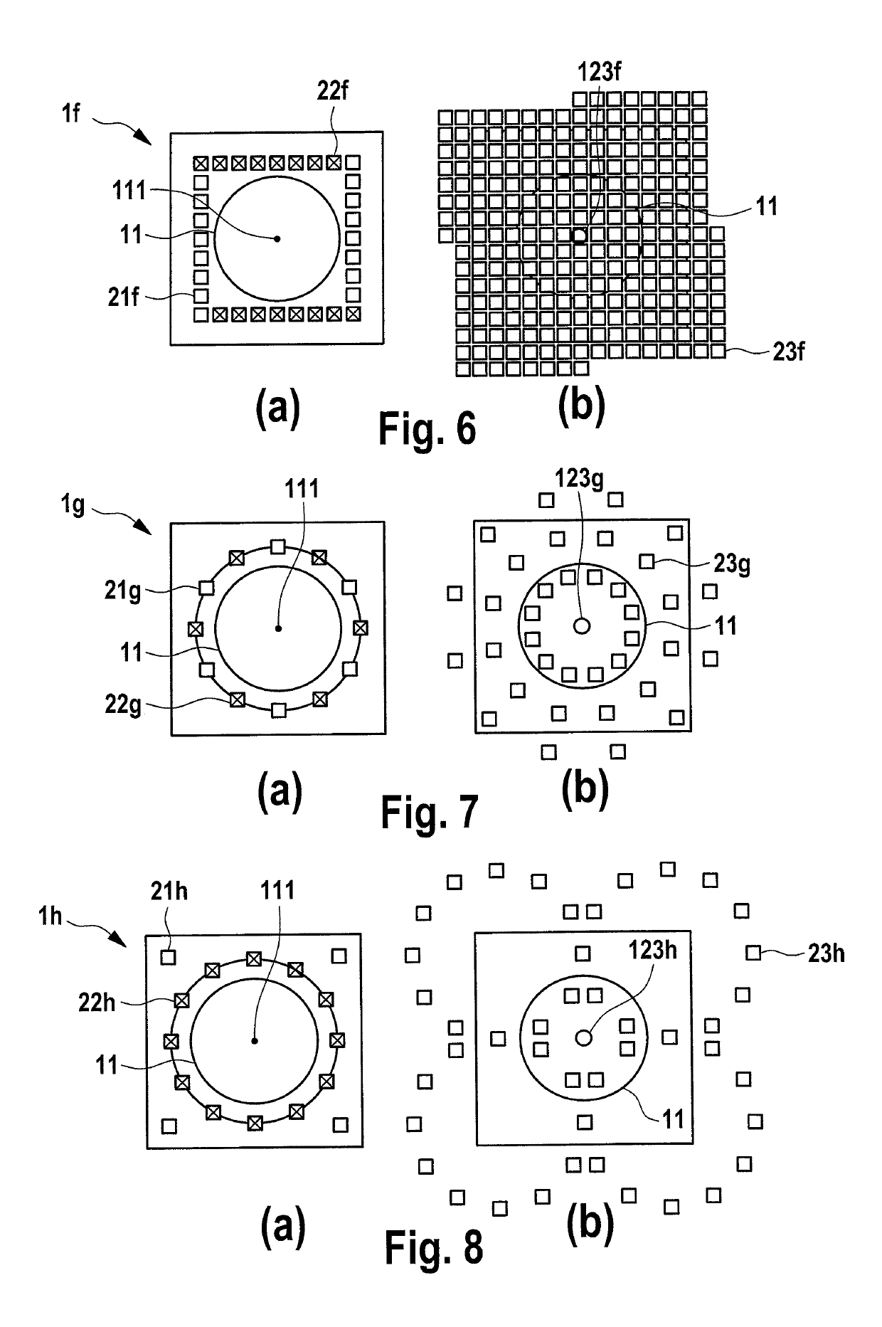
[0053]FIGS. 3 to 8 show a fourth to ninth embodiment of a surveillance apparatus 1c to 1h according to the present disclosure, particularly of the radar sensor and the camera aperture, according to which the antennas are arranged at the periphery of the camera aperture.

[0054]The embodiments 1c, 1d shown in FIGS. 3 and 4 each use a 1D MIMO antenna array having multiple Tx antennas 21c, 21d and multiple Rx antennas 22c, 22d. All the antennas cover the field of view of the optical camera. Each pair of Tx and Rx antennas is equal to one virtual antenna 23c, 23d (positioned at the spatial convolution of the real Tx and Rx antenna). All the combinations of Tx antenna and Rx antenna pairs are equal to a 1D virtual antenna array as shown in FIGS. 3(b), 4(b).

[0055]In the embodiment shown in FIG. 3(b), the center area 123c of the virtual antenna array coincides with the center area 111 (in particular the center point) of the camera aperture. In this configuration, the radar sensor and the opt...

embodiment 1

[0079]2. The surveillance apparatus ,

[0080]wherein said one or more transmitting antennas and said one or more receiving antennas are arranged on the periphery of the surveillance apparatus.


PUM


Abstract

A surveillance apparatus includes an optical camera that captures images based on received light, the optical camera including a camera aperture and a radar sensor including one or more transmitting antennas configured to emit electromagnetic radiation and one or more receiving antennas configured to receive electromagnetic radiation. The one or more transmitting antennas and the one or more receiving antennas form a virtual antenna array. The one or more transmitting antennas and the one or more receiving antennas are arranged such with respect to the optical camera that the center area of the virtual antenna array and the center area of the camera aperture coincide.

Description

CROSS-REFERENCE TO RELATED APPLICATIONS[0001]The present application is based on PCT filing PCT / EP2014 / 075027 filed Nov. 19, 2014, and claims priority to European Patent Application 13193769.0 filed by the European Patent Office on 19 Nov. 2014, the entire contents of each of which being incorporated herein by reference.BACKGROUND[0002]Field of the Disclosure[0003]The present disclosure relates to the field of surveillance cameras for safety and security applications. A surveillance apparatus, having an optical camera and an additional radar sensor, and a corresponding surveillance method are disclosed. Application scenarios include burglar, theft or intruder alarm as well as monitoring public and private areas, inside or outside.[0004]Description of Related Art[0005]Optical surveillance cameras are used in many public places such as train stations, stadiums, supermarkets and airports to prevent crimes or to identify criminals after they committed a crime. Optical surveillance camer...

Claims


Application Information

Patent Timeline
Patent Type & Authority Patents(United States)
IPC IPC(8): G01S7/02H01Q5/40H01Q5/22H01Q21/06G01S7/03H01Q1/22G01S13/86G01S13/02
CPCG01S13/867G01S7/03H01Q1/22H01Q5/40H01Q21/065H01Q5/22G01S2013/0245G01S2007/027G01S7/027
Inventor WANG, QIBLECH, MARCEL DANIELBOEHNKE, RALF
Owner SONY CORP
Why Eureka
Try Eureka